










Product Details
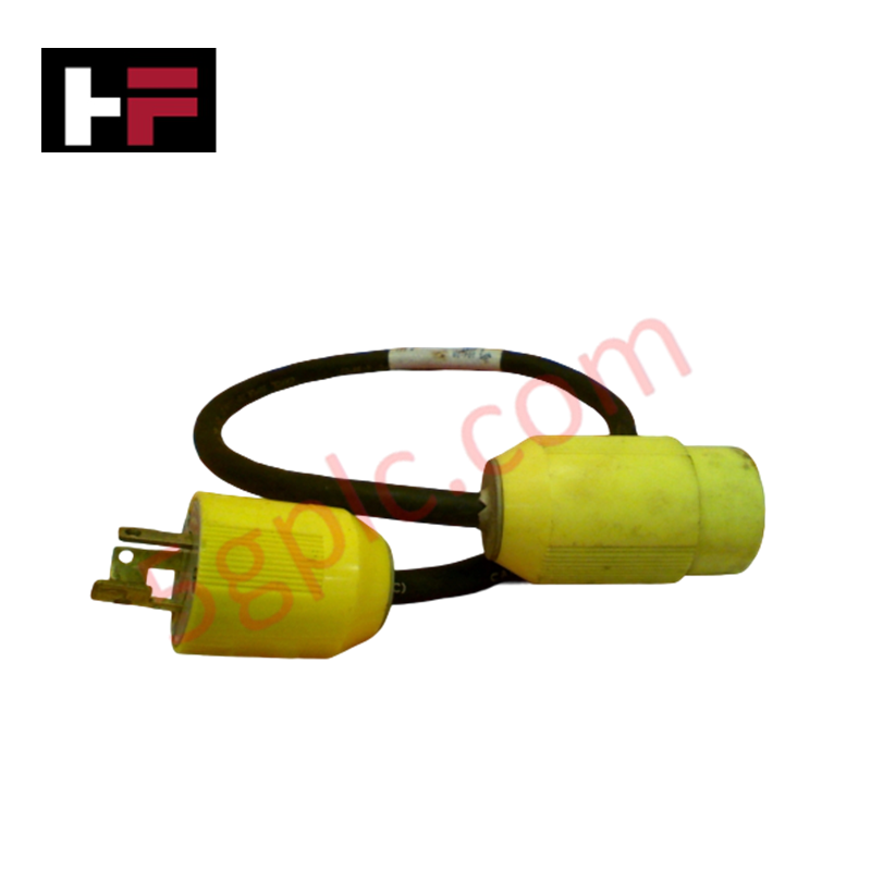
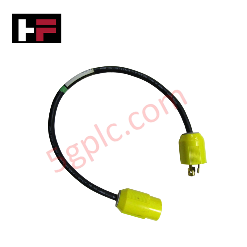
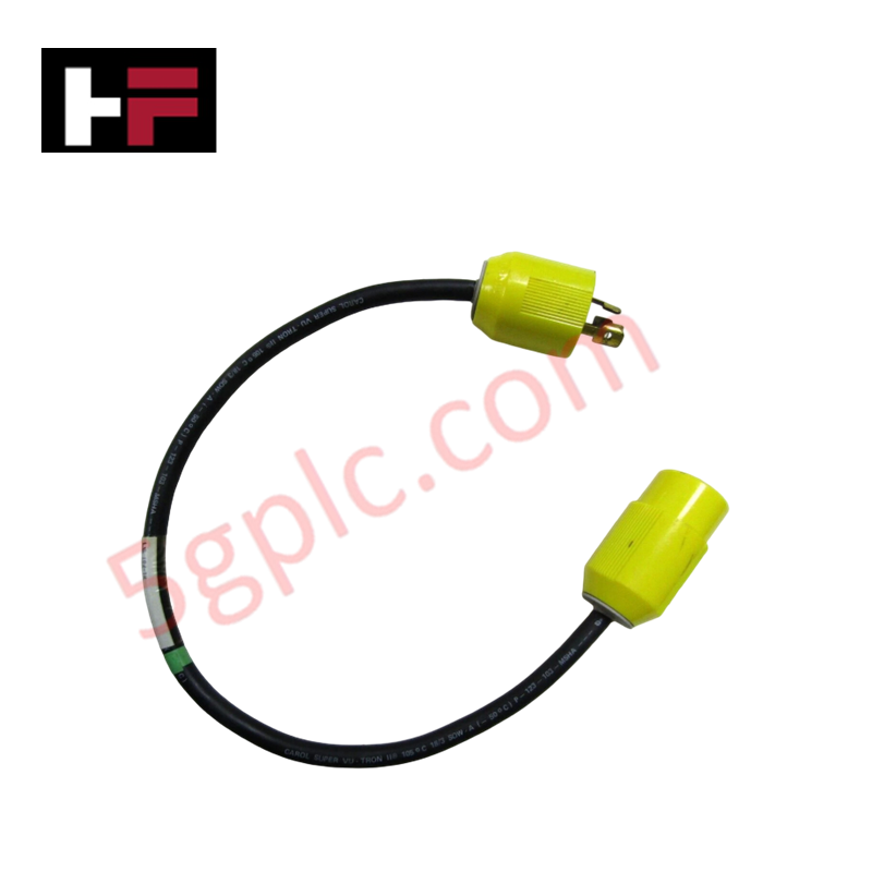
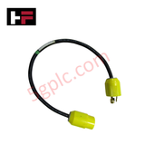
The Honeywell 51305490-600 serves as the primary 51305490-600 Communication Cable Assembly utilized to execute signal routing and data transfer across Experion PKS and TDC 3000 platforms. It establishes physical interconnection between controllers, I/O modules, and network nodes using shielded twisted-pair wiring to maintain differential signal integrity and mitigate electromagnetic interference in high-density cabinet backplanes.
Hardware Specifications
| Parameter | Specification |
|---|---|
| Model | 51305490-600 |
| Brand | Honeywell |
| Origin | USA |
| Weight | 0.5 kg |
| Dimensions | 1-3 m standard length (configurable) |
| Operating Temp | -20 to 60 deg C |
| Power Consumption | Passive cabling assembly (0 W internal) |
| Cable Type | Communication Cable Assembly |
| Cable Construction | Shielded twisted-pair (STP) wiring |
| Connector Type | Honeywell proprietary industrial connectors |
| Relative Humidity | 5% to 95% RH (non-condensing) |
| System Compatibility | Experion PKS, TDC 3000 DCS |
Process Control Signal Integrity & Channel-to-Channel Isolation
Industrial DCS environments require strict signal attenuation boundaries to maintain channel-to-channel isolation and overall control loop precision. The shielded twisted-pair construction of the assembly suppresses capacitive cross-talk and high-frequency noise injection originating from adjacent power conduits. This shielding profile preserves clean differential voltage transitions across serial and network buses, preventing communication frame loss and maintaining signal fidelity alongside parallel 4-20 mA HART loop protocol wiring.
Frequently Asked Questions
Q: Does the assembly feature an integrated drain wire for shield grounding through the connectors?
A: Shield continuity is maintained across the assembly via the proprietary industrial connector metal housings, establishing grounding through the chassis ground when mated to the module receptacle.
Q: Can this communication cable assembly be live-swapped during continuous system operation?
A: Cable replacement can be performed provided the connected communication channels reside on redundant buses; disconnecting a non-redundant active link will interrupt real-time module data scanning.
Field Installation Guidelines
- Power down connected non-redundant module slots prior to installing or removing the cable assembly to avoid transient communication faults.
- Route the cable through designated low-voltage signal raceways, maintaining a minimum physical clearance of 300 mm from AC power conductors and variable frequency drive output cables.
- Observe a minimum static bend radius of 8 times the outer cable diameter to avoid damaging internal conductors or shield wraps during panel installation.
- Align connector keyways precisely before applying axial insertion force to prevent pin bending inside module header sockets.
- Secure all strain-relief latches and mechanical retaining screws to withstand continuous operational vibration within the enclosure.
Additional Information
- 100% Genuine Parts: All products are original and authentic, ensuring reliable industrial performance.
- 30-Day Refund Guarantee: Return any in-stock item within 30 days in original, unopened packaging for a full refund (excluding shipping and fees).
- 12-Month Warranty: Covers defects in materials or workmanship; excludes misuse, normal wear, or unauthorized modifications.
- Worldwide Shipping: We ship via USPS, UPS, FedEx, and DHL. Delivery times vary by country and may be subject to customs or import fees.
- Support & Contact: Technical and warranty assistance is available anytime. Contact us here: Contact.
- Purchase Guidance: Check product specifications and compatibility carefully before ordering to ensure proper application.


Tech & Buying Guide

Essential Best Practices for PLC Wiring and Installation in Industrial Automation
Successful control system deployment begins with thoroughly reviewing manufacturer technical documentation. Controllers from major brands like Allen-Bradley, Siemens, and Schneider Electric feature unique terminal layouts. Engineers must verify voltage requirements before connecting power cables to prevent catastrophic equipment damage. Standard line connections require strict adherence to regional electrical codes and proper wire color coding. Furthermore, panel builders should always establish a robust low-impedance ground connection using at least 16-AWG copper conductor tied directly to the main plant grounding grid.

Demystifying Programmable Logic Controllers: Comprehensive Guide to PLC Classification and Selection in Industrial Automation
Modern industrial automation heavily relies on Programmable Logic Controllers (PLCs) to drive factory floor efficiency. Over my 15 years as an industrial automation expert working with DCS, TSI, and control systems, I have seen PLCs evolve into the central nervous system of modern manufacturing. Selecting the right controller requires a deep understanding of PLC types based on physical size, hardware architecture, and power supply configurations.

Comprehensive Guide to PLC Types in Modern Industrial Automation
Modern industrial automation relies on programmable logic controllers to govern critical factory operations. System integrators classify PLCs based on scale, hardware architecture, and power supply design. Understanding these core categories enables automation engineers to select the right control system architecture. Consequently, proper hardware selection optimizes performance while minimizing long-term operational costs.