


Product Details
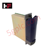
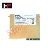
The Emerson 396509-05-3, also cataloged as the 396509-05-3 Power Supply Module, operates as a dedicated hardware component for continuous electrical regulation and voltage distribution within ControlWave hardware chassis platforms. The subassembly conditions raw input voltages, isolating downstream logic tracks and maintaining stabilized power allocation blocks for interconnected backplane logic arrays and peripheral field elements.
Hardware Specifications
| Parameter | Specification |
| Model | 396509-05-3 (Series A) |
| Brand | Emerson (ControlWave) |
| Origin | USA |
| Weight | 1.00 lbs |
| Dimensions | Standard ControlWave rack chassis module slot profile |
| Operating Temp | -40 deg C to +70 deg C |
| Power Input | +24 VDC Nominal |
| Power Consumption (Internal Logic) | 1000 mA at 24 VDC |
| Power Distribution (Field Circuits) | 3600 mA at 24 VDC |
| System Platform | ControlWave Micro/Chassis Infrastructure |
Distributed Control System Architecture and Channel-to-Channel Isolation
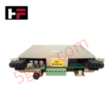
Mechanical execution of this Series A energy regulation module relies on localized physical isolation paths to stabilize backplane voltages. The internal circuit board layout enforces rigorous channel-to-channel isolation methods between the high-current field loop supply paths and sensitive computing elements. This independent tracking setup checks that electrical transients, line spikes, or short circuits on the 3600 mA field distribution array do not interface with internal logic rails, maintaining uncorrupted 4-20 mA HART loop protocol signalling across parallel processing cards.
Frequently Asked Questions
Q: Does this power module allow online hot-swap installation while the rack platform is active?
A: No. Removing or inserting a primary power supply module while the system is energized can induce localized backplane voltage drops or logic rail interruptions, resulting in the immediate crash of connected central processing units.
Q: How is the current capacity distributed between the logic and field circuit systems?
A: The module separates incoming power into two distinct subsystems, providing up to 1000 mA at 24 VDC exclusively for inner backplane logic operations and up to 3600 mA at 24 VDC to energize external field instrumentation loops.
Field Installation Guidelines
-
Chassis Slot Alignment: Slide the power supply module into the dedicated power slot of the ControlWave base housing along the tracking guides. Secure the integrated faceplate retaining hardware completely to ensure proper electrical engagement with the backplane grounding system.
-
Input Cable Terminations: Connect the incoming +24 VDC power conductors to the designated screw terminals. Check that the terminal screws are torqued down completely to eliminate high contact resistance anomalies.
-
Shield Ground Tracking: Terminate all external supply cable shields directly at the common industrial cabinet master grounding bar. Continuous single-point grounding methods must be used to block low-frequency common-mode noise from skewing data signals.
-
Thermal Environment Control: Verify that localized cooling clearance meets factory drawings, checking that airflow paths are unobstructed when operating near the upper boundary limit of +70 deg C to prevent thermal cutouts.
Additional Information
- 100% Genuine Parts: All products are original and authentic, ensuring reliable industrial performance.
- 30-Day Refund Guarantee: Return any in-stock item within 30 days in original, unopened packaging for a full refund (excluding shipping and fees).
- 12-Month Warranty: Covers defects in materials or workmanship; excludes misuse, normal wear, or unauthorized modifications.
- Worldwide Shipping: We ship via USPS, UPS, FedEx, and DHL. Delivery times vary by country and may be subject to customs or import fees.
- Support & Contact: Technical and warranty assistance is available anytime. Contact us here: Contact.
- Purchase Guidance: Check product specifications and compatibility carefully before ordering to ensure proper application.


Tech & Buying Guide

Essential Motion Control Commands: A Practical Guide for Engineers
Automation engineers often rely on precise position and speed control to drive modern factory machinery. Modern industrial systems, such as Programmable Logic Controllers (PLCs) and Distributed Control Systems (DCS), depend heavily on standardized motion instructions. Mastering these commands ensures operational safety, protects mechanical components, and optimizes cycle times across production lines.

The Role of Intrinsic Safety Barriers in PLC and DCS Architectures
Implementing robust protection in hazardous industrial environments represents a fundamental safety requirement in factory automation. Process facilities often handle volatile gases, dusts, and chemical agents that pose significant combustion risks. Consequently, control system engineers must deploy energy-limiting interfaces to isolate safe-area control cabinets from hazardous-area field instrumentation. This article examines the function, selection, and electrical principles of intrinsic safety barriers within modern PLC and DCS networks.

Architectural Selection and Scale Classification of PLC Systems in Industrial Automation
Selecting the correct control platform represents a foundational engineering decision in factory automation. System designers must carefully balance technical parameters against long-term operational requirements when implementing a Programmable Logic Controller (PLC). This article examines the critical evaluation metrics, physical scale classifications, and operational architectures of modern control systems.