


Product Details
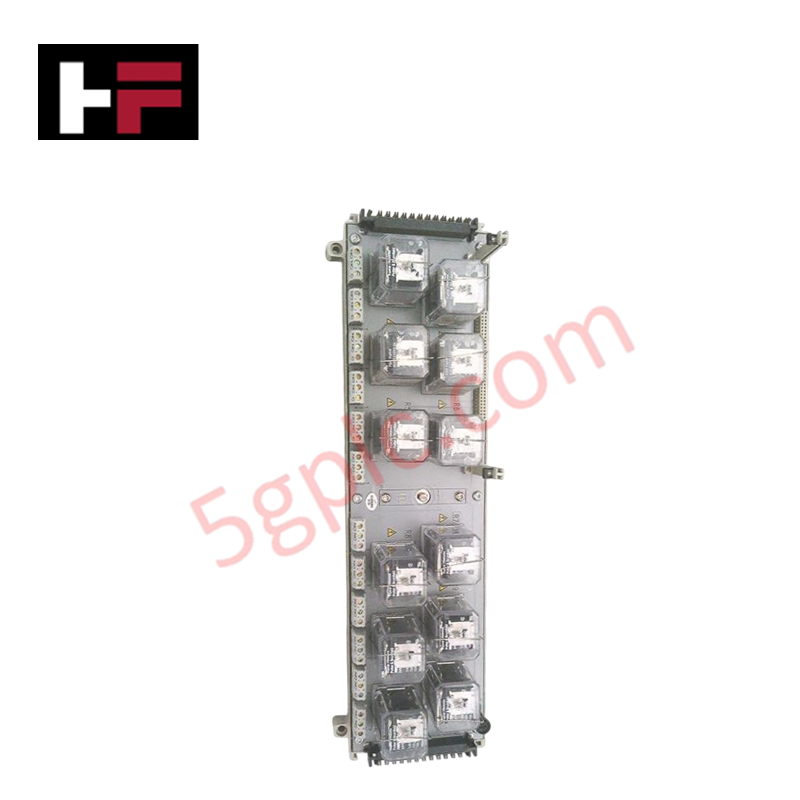
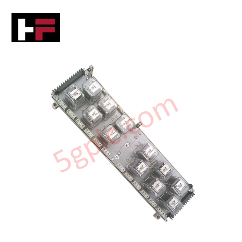
Configured for discrete interface termination in Ovation control platforms, the Emerson 1C31222G01 (1C31222G01 Relay Output Base) provides direct physical execution of relay mounting and field wiring distribution.
Hardware Specifications
| Parameter | Specification |
|---|---|
| Model | 1C31222G01 |
| Brand | Emerson |
| Origin | Manufacturer-defined |
| Weight | 1.95 kg |
| Dimensions | 30 cm x 20 cm x 25 cm |
| Operating Temp | Industrial standard range |
| Power Consumption | N/A (Passive base) |
| Function | Relay output termination base |
4-20 mA HART Loop Protocol
The 1C31222G01 functions as a passive interface base, facilitating the mounting of discrete relay output modules within the Ovation control cabinet. While this unit does not actively condition 4-20 mA HART loop protocol signals, it provides the physical structure necessary to route output contacts from the control modules to field devices. Channel-to-channel isolation is maintained through the base terminal layout, preventing electrical leakage between adjacent relay circuits. The modular design supports consistent wiring density and ensures that discrete output signals are routed through proper terminal points for field actuator control.
Frequently Asked Questions
Q: Is this relay base compatible with all Ovation digital output modules?
A: The 1C31222G01 is specific to defined relay output module footprints. Verify the compatibility of the control module part number with the base assembly to ensure correct alignment of the backplane connectors and signal terminal blocks.
Q: Does the relay base include integrated suppression for inductive loads?
A: The base assembly is a passive distribution component and does not include active surge suppression. Suppression for inductive field loads must be implemented at the terminal block level or via external components connected to the relay output circuit.
Field Installation Guidelines
- Secure the base to the cabinet mounting plate using appropriate hardware, ensuring the unit is level and aligned with adjacent I/O infrastructure.
- Terminate all field-side conductors to the base terminal strips, following the system wiring diagram to ensure correct channel mapping.
- Verify that the cable shielding is correctly grounded at the cabinet entry point to maintain signal integrity and meet EMI/RFI shielding requirements.
- Route field wiring through dedicated plastic wireways, maintaining separation from high-voltage AC power distribution to minimize electromagnetic coupling.
- Inspect all terminal connections for proper torque and mechanical stability before seating the control modules into the base assembly.
Additional Information
- 100% Genuine Parts: All products are original and authentic, ensuring reliable industrial performance.
- 30-Day Refund Guarantee: Return any in-stock item within 30 days in original, unopened packaging for a full refund (excluding shipping and fees).
- 12-Month Warranty: Covers defects in materials or workmanship; excludes misuse, normal wear, or unauthorized modifications.
- Worldwide Shipping: We ship via USPS, UPS, FedEx, and DHL. Delivery times vary by country and may be subject to customs or import fees.
- Support & Contact: Technical and warranty assistance is available anytime. Contact us here: Contact.
- Purchase Guidance: Check product specifications and compatibility carefully before ordering to ensure proper application.


Tech & Buying Guide

Essential Motion Control Commands: A Practical Guide for Engineers
Automation engineers often rely on precise position and speed control to drive modern factory machinery. Modern industrial systems, such as Programmable Logic Controllers (PLCs) and Distributed Control Systems (DCS), depend heavily on standardized motion instructions. Mastering these commands ensures operational safety, protects mechanical components, and optimizes cycle times across production lines.

The Role of Intrinsic Safety Barriers in PLC and DCS Architectures
Implementing robust protection in hazardous industrial environments represents a fundamental safety requirement in factory automation. Process facilities often handle volatile gases, dusts, and chemical agents that pose significant combustion risks. Consequently, control system engineers must deploy energy-limiting interfaces to isolate safe-area control cabinets from hazardous-area field instrumentation. This article examines the function, selection, and electrical principles of intrinsic safety barriers within modern PLC and DCS networks.

Architectural Selection and Scale Classification of PLC Systems in Industrial Automation
Selecting the correct control platform represents a foundational engineering decision in factory automation. System designers must carefully balance technical parameters against long-term operational requirements when implementing a Programmable Logic Controller (PLC). This article examines the critical evaluation metrics, physical scale classifications, and operational architectures of modern control systems.