










Product Details
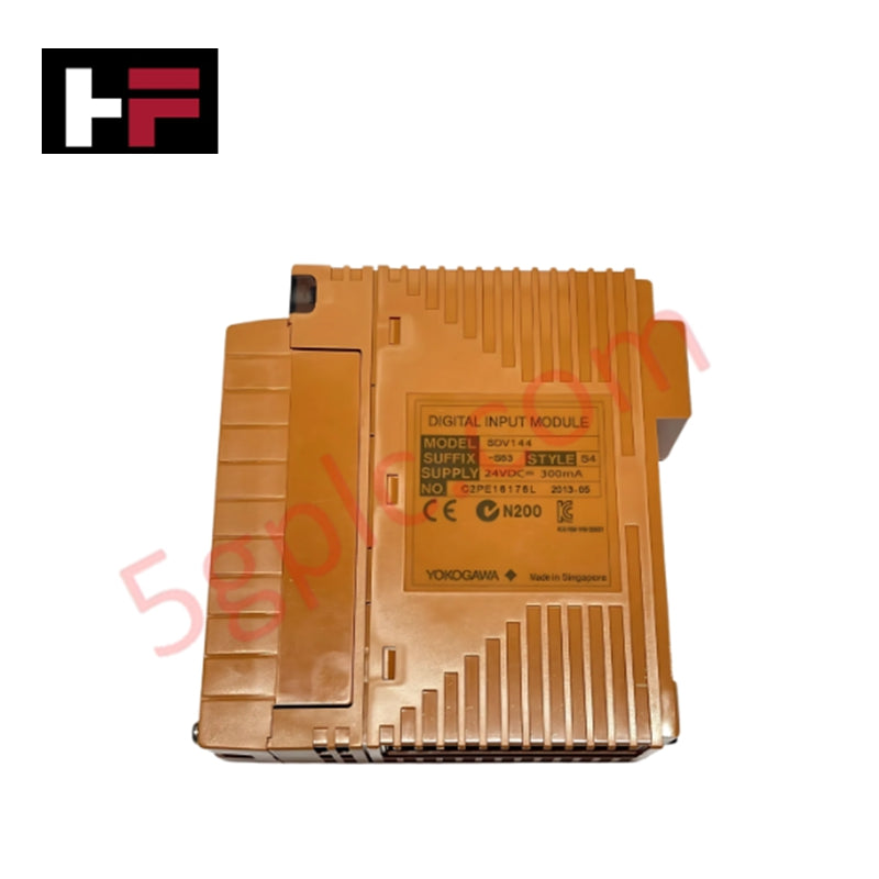
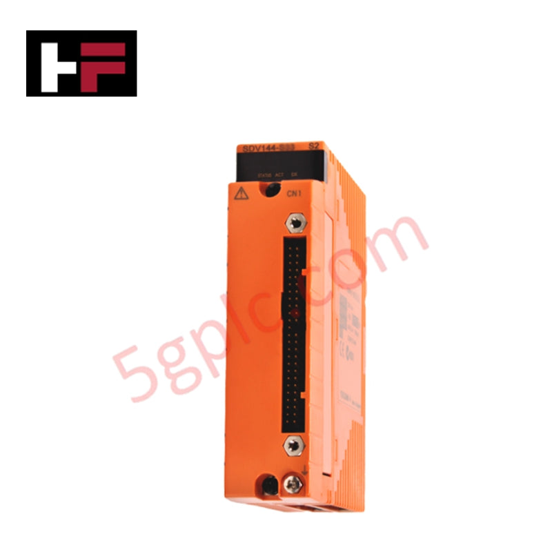
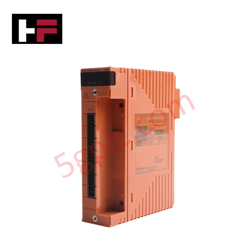
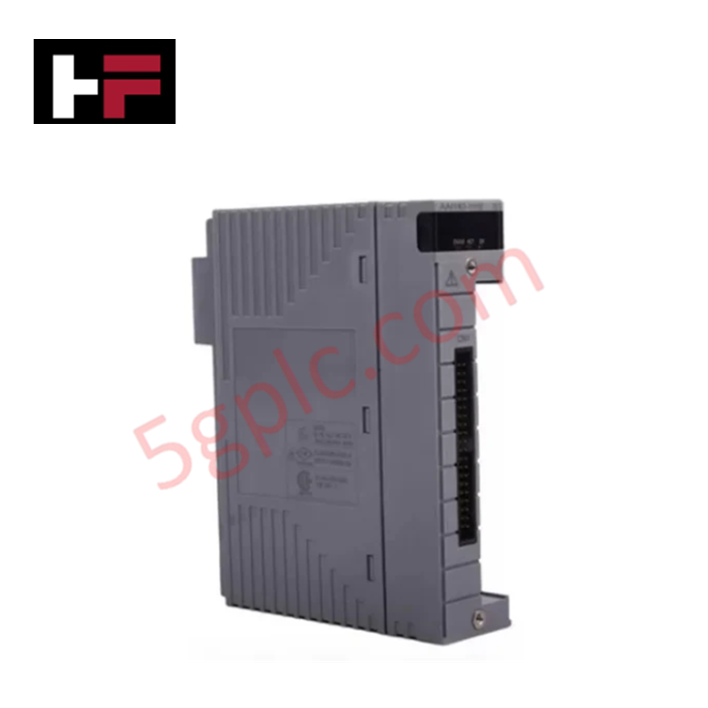
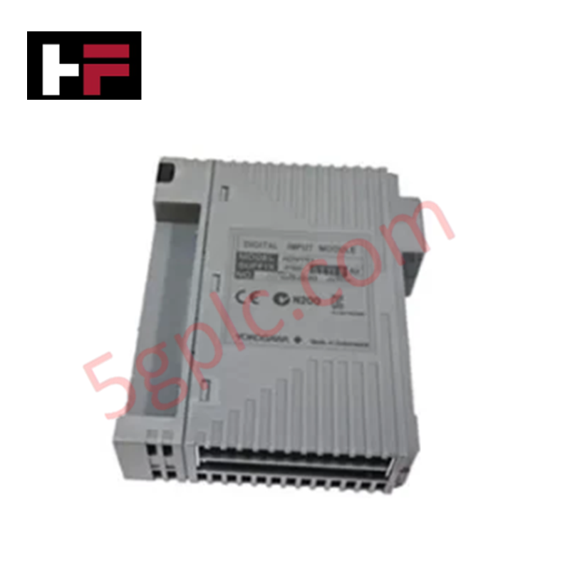
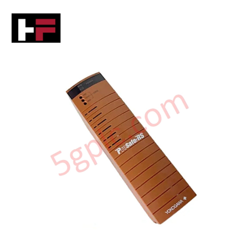
The YOKOGAWA SDV144-S13/B4D00, also cataloged as the YOKOGAWA SDV144 Digital Input Module, operates as a dedicated hardware component for isolated binary status monitoring within ProSafe-RS safety instrumented system platforms. The assembly interrogates 16 discrete channels of field dry contact circuits via integrated 24 VDC wetting voltage, delivering verified input status transitions to the processing logic bus within bounded scan windows.
Hardware Specifications
| Parameter | Specification |
|---|---|
| Model | SDV144-S13/B4D00 |
| Brand | YOKOGAWA |
| Origin | Japan |
| Weight | 0.36 kg (with pressure clamp terminal block / MIL cable); 0.41 kg (with signal cable interface adapter) |
| Dimensions | Standard Yokogawa ProSafe-RS I/O module physical enclosure profile |
| Operating Temp | 0 to +60 deg C (Standard baseline operating environment) |
| Power Consumption | 290 mA maximum @ 5 VDC, 140 mA maximum @ 24 VDC from the system backplane |
| Input Channels | 16 isolated channels |
| Input Signal Type | No-voltage contact (Dry contact) |
| ON State Resistance | 1 k ohm maximum |
| OFF State Resistance | 100 k ohm minimum |
| Input Loop Current | 6 mA +/-20% at 24 VDC (0 ohm input loop condition) |
| External Contact Wetting | 24 VDC (+20% / -10%) external distribution supply |
| External Current Capacity | 200 mA minimum required supply reserve |
| Peak Input Voltage Tolerance | 30 VDC instantaneous maximum permissible limit |
| Hardware Response Time | 40 ms maximum input signal acquisition delay |
| Dielectric Withstand Voltage | 2 kV AC for 1 minute between field-side input signal loops and internal system logic |
| Physical Connections | Options for pressure clamp terminal blocks, MIL ribbon cable, or AKB331 dedicated signal cable |
Safety Control & Channel-to-Channel Isolation
The module infrastructure relies on independent galvanic isolation architecture designed to execute strict input channel separation. By running discrete signal lines through internal optocouplers, high-voltage field spikes or transient fault loops up to 2 kV AC are restricted to the field terminal interface, preventing cascade damage to the core processing electronics. This architecture guarantees proper signal demarcation within safety-instrumented loops, suppressing cross-talk and protecting the execution path of critical emergency shutdown commands.
Frequently Asked Questions
Q: Does the module detect field circuit degradation before an ON/OFF state change fails?
A: State transition relies strictly on the threshold boundaries of the ON resistance (1 k ohm maximum) and OFF resistance (100 k ohm minimum). Field loop degradation that shifts resistance into the intermediate zone between these values will delay acquisition beyond the 40 ms window or generate a diagnostic status fault on the safety bus.
Q: Can this module be hot-swapped while the ProSafe-RS safety system is actively executing code?
A: Hot-swapping is physically supported by the module backplane layout. However, safety engineering procedures dictate that the specific 16-channel loop configuration must be bypassed within the ProSafe-RS logic beforehand to prevent spontaneous safe-state system trips during physical removal or insertion of the module.
Field Installation Guidelines
- Wiring Method Segregation: Field wiring terminations must utilize the pressure clamp terminal assembly or the specialized AKB331 interface cable matrix. Safety-critical digital inputs must be physically segregated from high-power AC lines within the cable routing trays to eliminate electromagnetic signal coupling.
- Shield Grounding Conventions: All external signal cable shields must be stripped, bundled, and directly connected to the dedicated master cabinet ground busbar. Shields must remain floating at the field device end to suppress common-mode ground loops from injecting electrical offsets into the 24 VDC wetting circuits.
- Thermal Management and Airflow: Mount the unit vertically onto the ProSafe-RS I/O baseplate slot, ensuring the physical retention latches lock cleanly into place. Ensure adjacent module power cables do not obstruct the vertical convective airflow pathways across the component housing.
Additional Information
- 100% Genuine Parts: All products are original and authentic, ensuring reliable industrial performance.
- 30-Day Refund Guarantee: Return any in-stock item within 30 days in original, unopened packaging for a full refund (excluding shipping and fees).
- 12-Month Warranty: Covers defects in materials or workmanship; excludes misuse, normal wear, or unauthorized modifications.
- Worldwide Shipping: We ship via USPS, UPS, FedEx, and DHL. Delivery times vary by country and may be subject to customs or import fees.
- Support & Contact: Technical and warranty assistance is available anytime. Contact us here: Contact.
- Purchase Guidance: Check product specifications and compatibility carefully before ordering to ensure proper application.
Tech & Buying Guide

Executing a PLC System Site Acceptance Test (SAT): The Definitive Engineering Guide
The transition of a Programmable Logic Controller (PLC) cabinet from a controlled factory floor to a volatile plant environment represents a critical milestone in factory automation. While a Factory Acceptance Test (FAT) validates standalone hardware compliance under ideal conditions, it cannot replicate real-world process dynamics. Therefore, deploying an industrial automation system requires a rigorous Site Acceptance Test (SAT) to verify total loop integrity, field wiring wiring metrics, and process control parameters before final customer handover.

Advanced Integration: Master Protocol for VFD Commissioning and Testing
Deploying variable frequency drives (VFDs) requires precise execution during the initial commissioning phase. Junior automation engineers often find the first power-up sequence intimidating. However, following a rigorous engineering framework ensures equipment safety and system reliability. Proper startup procedures protect both the drive electronics and the connected motor.

Optimizing Factory Automation: The Definitive Guide to VFD Preventive Maintenance
Variable Frequency Drives (VFDs) serve as critical assets in modern industrial automation. These power electronic devices regulate electric motors by adjusting the supplied frequency and voltage. Consequently, industries utilize VFDs to reduce energy consumption and optimize process control. Major manufacturers like Siemens, ABB, and Yaskawa design highly efficient drives. However, sustained efficiency requires a rigorous preventive maintenance program.