










Product Details
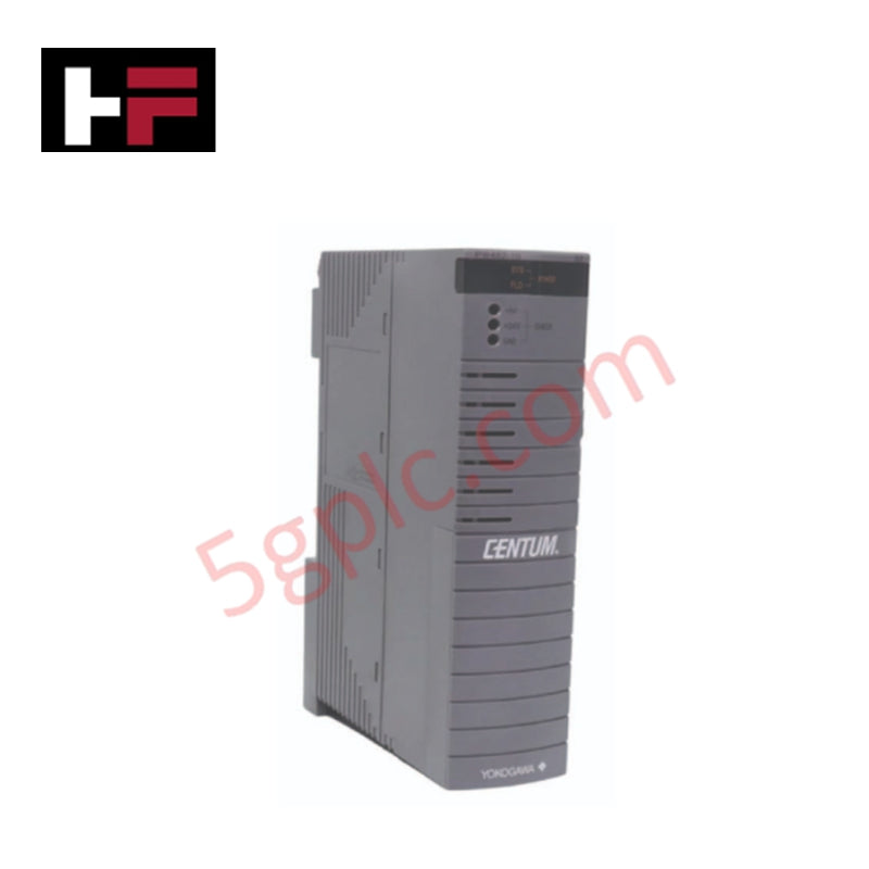
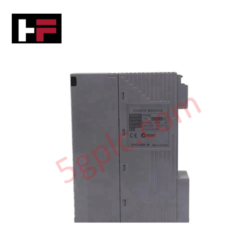
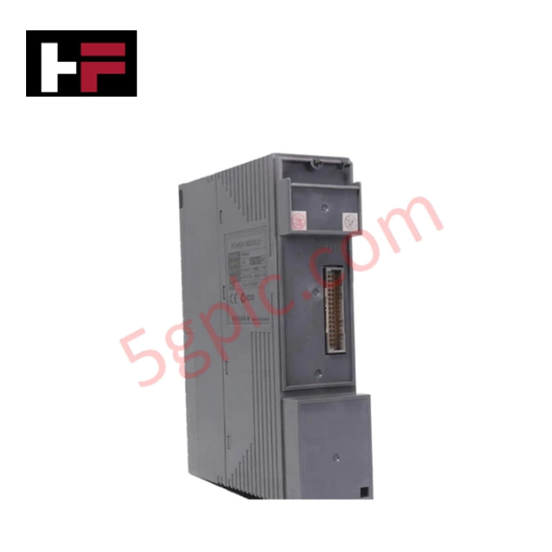
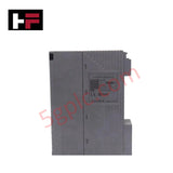
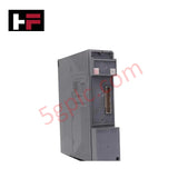
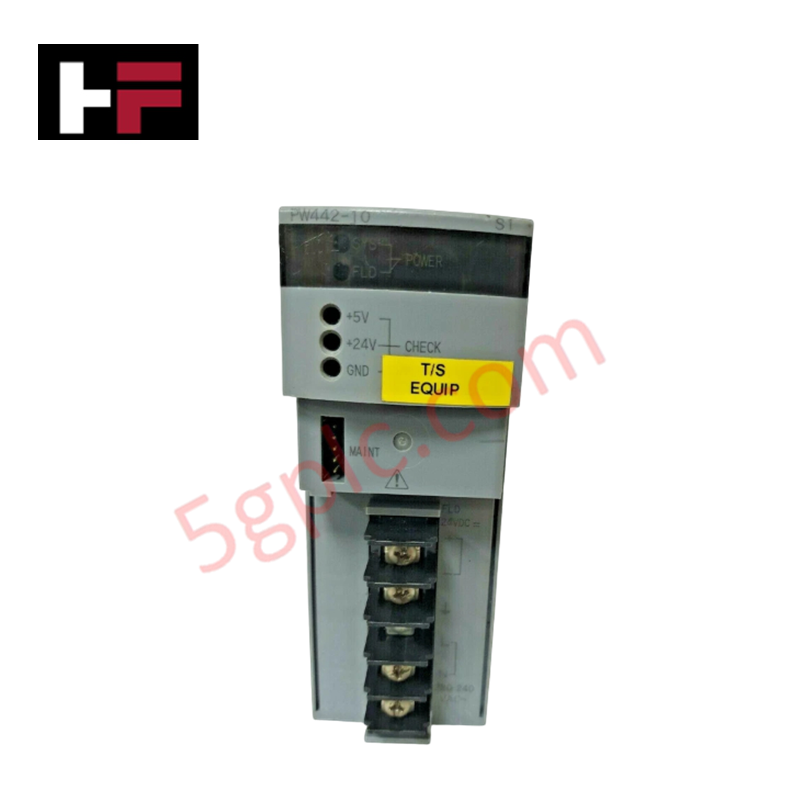
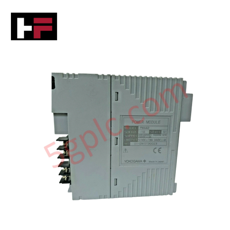
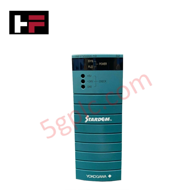
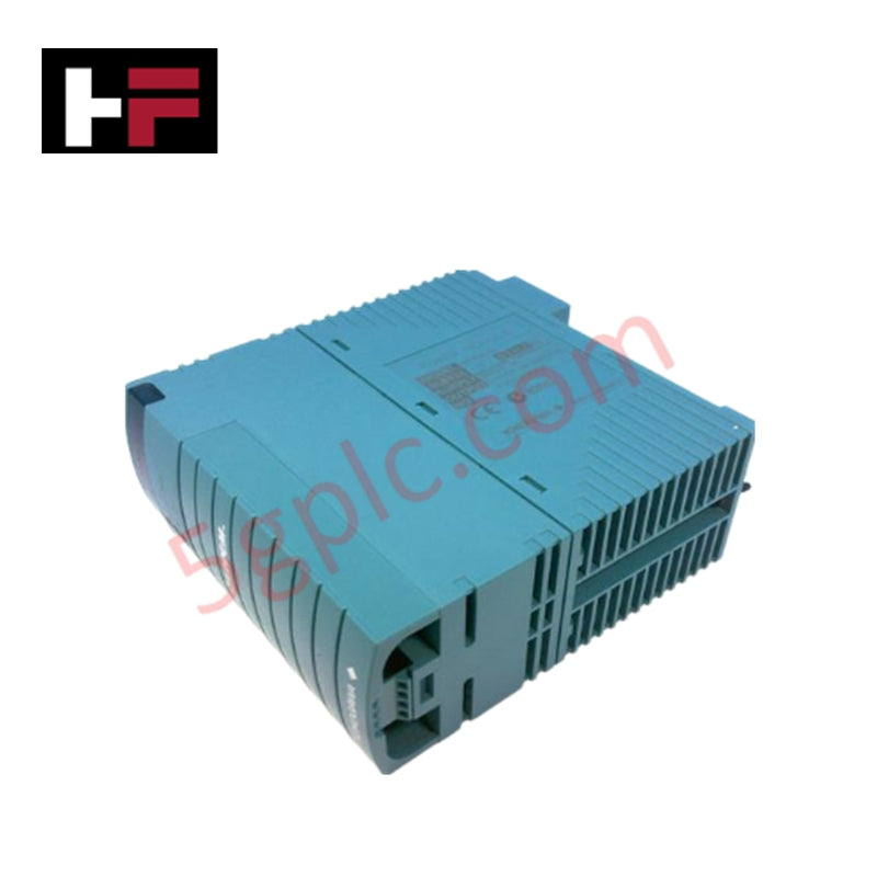
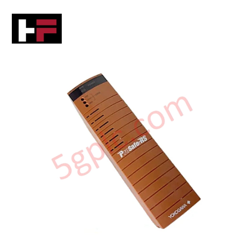
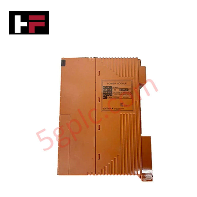
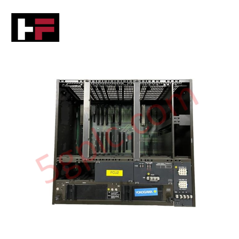
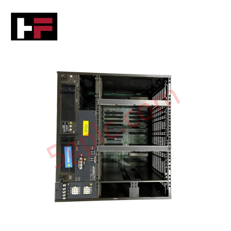
The Yokogawa PW482-S01, also cataloged as the PW482 Power Supply Module, operates as a dedicated hardware component for localized electrical power transformation and stabilization within Yokogawa system networks. The module interfaces directly with the backplane bus infrastructure to convert primary source voltages into regulated secondary direct-current outputs for adjacent system nodes.
Hardware Specifications
| Parameter | Specification |
|---|---|
| Model | PW482-S01 |
| Brand | Yokogawa |
| Origin | USA |
| Weight | 0.9 kg |
| Dimensions | 5.1 cm x 20.3 cm x 15.2 cm |
| Operating Temp | Standard industrial operating limits (refer to base enclosure manuals) |
| Power Consumption | Load-dependent based on hardware backplane configuration |
| Product Type | Power Supply Module |
Process Control & Channel-to-Channel Isolation
The infrastructure of the power architecture establishes a localized grounding matrix that implements high-grade channel-to-channel isolation parameters. By segmenting internal conversion topologies from external loop networks, the module intercepts and decouples transient electrical spikes before they penetrate the internal data registers. This isolation reduces high-frequency cross-talk interference and provides noise attenuation, stabilizing the 4-20 mA HART loop protocol signaling that propagates through downstream analytical and control instrumentation loops.
Frequently Asked Questions
Q: What are the functional limitations concerning online hot-swapping for this power supply module?
A: Hot-swapping is permitted only when the module is deployed within a dual-redundant power supply configuration where the parallel unit actively carries the entire backplane load. If a standalone single-configuration unit is extracted while energized, it will instantly cut power to the node, terminating active logic execution.
Q: How does the unit internally manage fluctuating primary supply line voltages?
A: The internal hardware architecture incorporates automatic voltage regulation circuits combined with inductive filtering stages. This framework handles input tolerances within standard engineering limits, suppressing line dips or swells before they influence internal DC voltage buses.
Field Installation Guidelines
- Mechanical Slot Alignment and Mounting: Position the module within the designated rack location and slide it inward along the chassis guides until the integrated connectors seat into the backplane. Tighten all retaining fasteners to secure the unit against environmental mechanical vibration.
- Shielding and Ground Terminal Bonding: Ensure the structural rack grounding plane bonds to the master station low-impedance copper ground network. All external instrumentation drain wires must terminate at the localized ground bus to prevent stray ground loop currents from injecting electrical noise.
- Thermal Management Clearance: Maintain unhindered vertical convective airflow streams above and below the module enclosure. Do not block the integrated physical ventilation pathways to ensure proper heat dissipation metrics during maximum power output periods.
Additional Information
- 100% Genuine Parts: All products are original and authentic, ensuring reliable industrial performance.
- 30-Day Refund Guarantee: Return any in-stock item within 30 days in original, unopened packaging for a full refund (excluding shipping and fees).
- 12-Month Warranty: Covers defects in materials or workmanship; excludes misuse, normal wear, or unauthorized modifications.
- Worldwide Shipping: We ship via USPS, UPS, FedEx, and DHL. Delivery times vary by country and may be subject to customs or import fees.
- Support & Contact: Technical and warranty assistance is available anytime. Contact us here: Contact.
- Purchase Guidance: Check product specifications and compatibility carefully before ordering to ensure proper application.
Tech & Buying Guide

Executing a PLC System Site Acceptance Test (SAT): The Definitive Engineering Guide
The transition of a Programmable Logic Controller (PLC) cabinet from a controlled factory floor to a volatile plant environment represents a critical milestone in factory automation. While a Factory Acceptance Test (FAT) validates standalone hardware compliance under ideal conditions, it cannot replicate real-world process dynamics. Therefore, deploying an industrial automation system requires a rigorous Site Acceptance Test (SAT) to verify total loop integrity, field wiring wiring metrics, and process control parameters before final customer handover.

Advanced Integration: Master Protocol for VFD Commissioning and Testing
Deploying variable frequency drives (VFDs) requires precise execution during the initial commissioning phase. Junior automation engineers often find the first power-up sequence intimidating. However, following a rigorous engineering framework ensures equipment safety and system reliability. Proper startup procedures protect both the drive electronics and the connected motor.

Optimizing Factory Automation: The Definitive Guide to VFD Preventive Maintenance
Variable Frequency Drives (VFDs) serve as critical assets in modern industrial automation. These power electronic devices regulate electric motors by adjusting the supplied frequency and voltage. Consequently, industries utilize VFDs to reduce energy consumption and optimize process control. Major manufacturers like Siemens, ABB, and Yaskawa design highly efficient drives. However, sustained efficiency requires a rigorous preventive maintenance program.