










Product Details
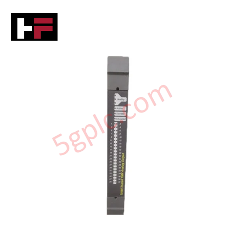
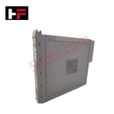
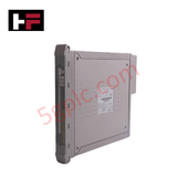
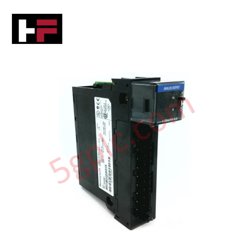
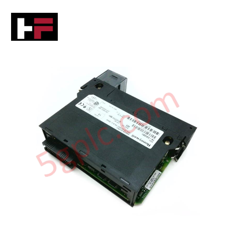
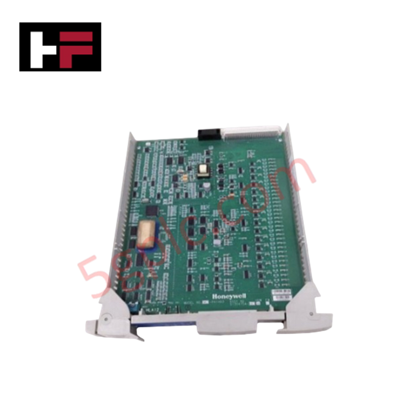
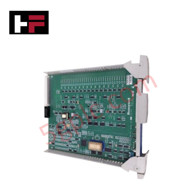
Configured for high-integrity discrete load switching in safety-critical ESD and shutdown systems, the ICS Triplex T8451 (T8451 Digital Output Module) provides direct physical/electrical execution. The module drives up to 40 field-side channels partitioned into 5 independent power groups over an operational voltage range of 18 VDC to 32 VDC.
Hardware Specifications
| Parameter | Specification |
|---|---|
| Model | T8451 |
| Brand | ICS Triplex |
| Origin | United Kingdom |
| Weight | 1.13 kg (Shipping Weight: 3.0 kg) |
| Dimensions | 300 mm x 30 mm x 241 mm (11.8 in x 1.2 in x 9.5 in) |
| Operating Temp | -5 deg C to +60 deg C (+23 deg F to +140 deg F) |
| Power Consumption | 24 W (System Supply) / 24 W (Field Supply @ 1 A/ch) |
| System Supply Voltage | 20 VDC to 32 VDC |
| Operational Field Voltage | 18 VDC to 32 VDC (Max Withstanding: -1 VDC to +40 VDC) |
| Output Channels | 40 Channels (5 Power Groups of 8 outputs) |
| Continuous Current Rating | 2 A per channel (Max 8 A per power group) |
| Minimum On-State Load | 50 mA |
| On-State Resistance | 0.6 Ohm |
| Output Turn-On/Off Delay | 0.5 ms |
| Sample Update Time | 0.5 ms |
| Field Common Isolation | +/-250 VDC Sustained Working / +/-2.5 kVDC Max Withstanding |
| Operating Humidity | 5% to 95% RH non-condensing |
High-Reliability Safety Control & TMR Architecture
The T8451 incorporates a triple modular redundancy (TMR) 2oo3 fault-tolerant architecture to achieve SIL3 certification within high-availability safety execution loops. Triplicated output channels utilize internal voter circuits and automatic electronic latching short-circuit protection to maintain continuous fail-safe state execution without dropping active control loops. Field-common galvanic isolation rated at +/-250 VDC sustained working voltage suppresses cross-talk and ground potential shifts, ensuring process field outputs execute deterministic shutoff logic during system fault events.
Frequently Asked Questions
Q: What are the current distribution limits per channel and per power group on the T8451 module?
A: Each individual output channel supports a maximum continuous load of 2 A, with the total combined load capped at 8 A per power group across the 5 independent output groups.
Q: How does the T8451 respond to an overcurrent or output short-circuit condition?
A: The module features automatic, electronic latching short-circuit protection that isolates the faulted channel to protect output switching hardware and surrounding control circuitry.
Q: Is external isolation required for installation of the T8451 in hazardous location field loops?
A: Yes. The module does not contain built-in intrinsic safety barriers; external Ex-i barriers must be wired in series with field loops requiring intrinsic safety protection.
Field Installation Guidelines
- Isolate field power and verify the 18 VDC to 32 VDC field voltage source before inserting the module into the active chassis slot.
- Ensure field load currents remain above the 50 mA minimum on-state threshold to maintain valid channel diagnostic state sensing.
- Route field output cables away from high-voltage AC lines to maintain channel-to-channel crosstalk suppression better than -40 dB.
- Securely seat the module retaining hardware into the rack frame to guarantee low-impedance frame grounding and continuous +/-2.5 kVDC isolation withstand capability.
Additional Information
- 100% Genuine Parts: All products are original and authentic, ensuring reliable industrial performance.
- 30-Day Refund Guarantee: Return any in-stock item within 30 days in original, unopened packaging for a full refund (excluding shipping and fees).
- 12-Month Warranty: Covers defects in materials or workmanship; excludes misuse, normal wear, or unauthorized modifications.
- Worldwide Shipping: We ship via USPS, UPS, FedEx, and DHL. Delivery times vary by country and may be subject to customs or import fees.
- Support & Contact: Technical and warranty assistance is available anytime. Contact us here: Contact.
- Purchase Guidance: Check product specifications and compatibility carefully before ordering to ensure proper application.


Tech & Buying Guide

Wellhead Control Panel (WHCP) Architecture in Oil and Gas Automation
Upstream oil and gas operations rely on specialized field control platforms to manage wellhead extraction safety and hydraulic actuation. A Wellhead Control Panel (WHCP) serves as a dedicated hydraulic and pneumatic power unit designed to operate critical Christmas Tree isolation valves. By interfacing field safety components directly with Programmable Logic Controller (PLC) architecture, a WHCP protects upstream extraction assets against overpressure, catastrophic leaks, and thermal emergencies.

Understanding Marshalling Cabinets in Industrial Control Systems Architecture
Industrial control system deployments rely on structured signal distribution to bridge field instrumentation with central processing hardware. A marshalling cabinet serves as the vital intermediate connection point between heavy field home-run multi-pair cables and delicate input/output (I/O) modules housed inside Programmable Logic Controller (PLC) or Distributed Control System (DCS) enclosures. By segregating field cable terminations from control hardware, engineers maintain system flexibility, safeguard controller components, and streamline commissioning workflows.

FAT vs SAT in Industrial Control Systems: Key Differences and Execution Guide
Industrial control system deployment relies on strict verification protocols to guarantee operational safety, system stability, and regulatory compliance. Commissioning complex Programmable Logic Controller (PLC) racks, Distributed Control Systems (DCS), and Safety Instrumented Systems (SIS) requires two critical milestones: the Factory Acceptance Test (FAT) and the Site Acceptance Test (SAT). Both procedures validate that system automation meets design specifications, but they occur at different stages of project execution and target distinct operational risks.