


Product Details
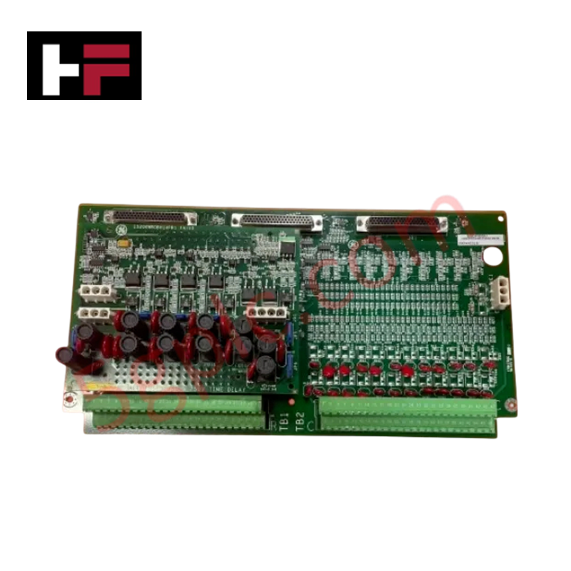
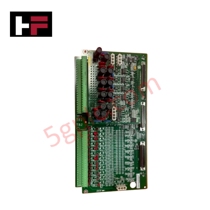
Configured for discrete signal management and relay-based control within Mark VIe architectures, the GE IS200TDBTH6A (IS200TDBTH6A Discrete Input/Output Terminal Board) provides direct physical and electrical execution of multi-channel I/O signal routing.
Hardware Specifications
| Parameter | Specification |
|---|---|
| Model | IS200TDBTH6A |
| Brand | General Electric |
| Origin | USA |
| Weight | Standard terminal board assembly |
| Dimensions | 17.8 cm x 33.02 cm |
| Operating Temp | -30 deg C to 65 deg C |
| Power Consumption | +5 VDC (Control), 24 VDC (I/O) |
| Digital I/O | 24 channels |
| Relay Channels | 12 |
Profinet / EtherNet/IP Deterministic Networks
The IS200TDBTH6A serves as a critical interface node within the Mark VIe control platform, enabling deterministic signal processing for discrete field instrumentation. The board integrates hardware-based input filtering to mitigate noise and provides a rejection capability of 12 V RMS for incoming AC voltage interference. Backplane bus communication velocity is optimized to ensure that state changes across the 24 digital channels and 12 relay outputs are processed within specified scan cycles. Firmware flash compatibility is managed via the host I/O pack, ensuring that logic transitions remain synchronized with system timing requirements. The board supports I/O density scaling through its compact surface-mount architecture, allowing for high-density relay control without compromising signal integrity.
Frequently Asked Questions
Q: Is the IS200TDBTH6A board hot-swappable while the system is energized?
A: No. Replacement of this terminal board must be performed with the control rack de-energized to prevent electrical shorts or backplane communication bus corruption.
Q: Are the 12 relay channels isolated from the 24 digital I/O channels?
A: The board design requires correct field wiring and shielding practices to ensure isolation between high-power relay switching circuits and low-power digital signal inputs.
Field Installation Guidelines
- Mounting: Secure the board using the designated mounting points within the control cabinet. Ensure adequate clearance from high-voltage cabling to prevent inductive noise on the discrete signal paths.
- Wiring: Terminate all digital I/O and relay connections to the terminal blocks. Use shielded cabling for long cable runs, and terminate shields at the cabinet grounding bus to suppress common-mode interference.
- Relay Loading: Verify that the current and voltage ratings of the external loads connected to the 12 relay channels do not exceed the board's rated switching capacity. Use suppression diodes when switching inductive loads to extend relay contact life.
- Environment: Maintain the ambient operating temperature between -30 deg C and 65 deg C. Ensure cabinet airflow is sufficient to dissipate heat generated during high-duty relay switching operations.
- Verification: Prior to commissioning, confirm the logic mapping for all 24 digital channels and 12 relay outputs via the Mark VIe configuration software. Perform a continuity check on all field wiring before energizing the I/O circuits.
Additional Information
- 100% Genuine Parts: All products are original and authentic, ensuring reliable industrial performance.
- 30-Day Refund Guarantee: Return any in-stock item within 30 days in original, unopened packaging for a full refund (excluding shipping and fees).
- 12-Month Warranty: Covers defects in materials or workmanship; excludes misuse, normal wear, or unauthorized modifications.
- Worldwide Shipping: We ship via USPS, UPS, FedEx, and DHL. Delivery times vary by country and may be subject to customs or import fees.
- Support & Contact: Technical and warranty assistance is available anytime. Contact us here: Contact.
- Purchase Guidance: Check product specifications and compatibility carefully before ordering to ensure proper application.


Tech & Buying Guide

Why 24V DC Power Supplies Standardize Modern Industrial Automation
Industrial control cabinets worldwide rely on 24V DC as the universal power standard for field instrumentation, sensors, and controllers. Walk into any manufacturing plant, and you will find PLCs, human-machine interfaces (HMIs), and smart actuators running on extra-low voltage DC. Standardizing on 24V DC enhances operational safety, lowers cabinet footprint, and maintains steady control performance across factory networks.

Essential Motion Control Commands: A Practical Guide for Engineers
Automation engineers often rely on precise position and speed control to drive modern factory machinery. Modern industrial systems, such as Programmable Logic Controllers (PLCs) and Distributed Control Systems (DCS), depend heavily on standardized motion instructions. Mastering these commands ensures operational safety, protects mechanical components, and optimizes cycle times across production lines.

Mastering Modern Industrial Joystick Controls in Heavy Automation
Industrial joysticks play a pivotal role in human-machine interaction across heavy material handling and mobile hydraulics. These tactile controllers translate complex operator movements into precise electrical signals for PLCs, motion controllers, and DCS networks. Consequently, selecting and installing the right joystick architecture ensures operator safety, reduces fatigue, and optimizes equipment performance.