


Product Details
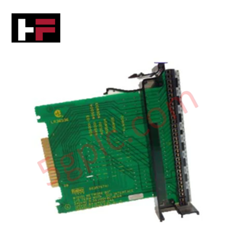
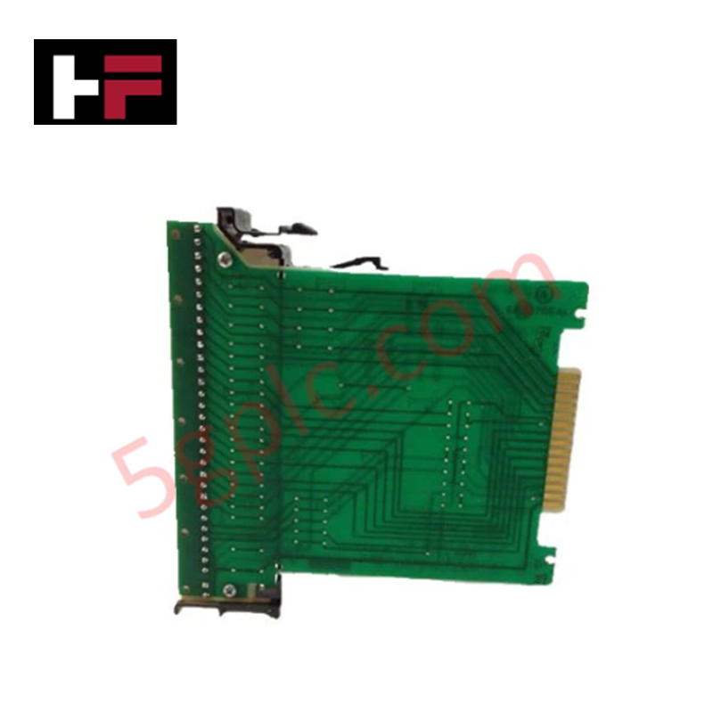
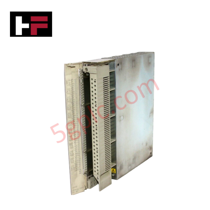
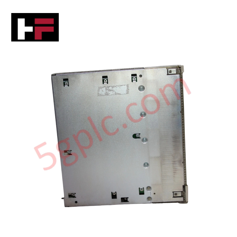
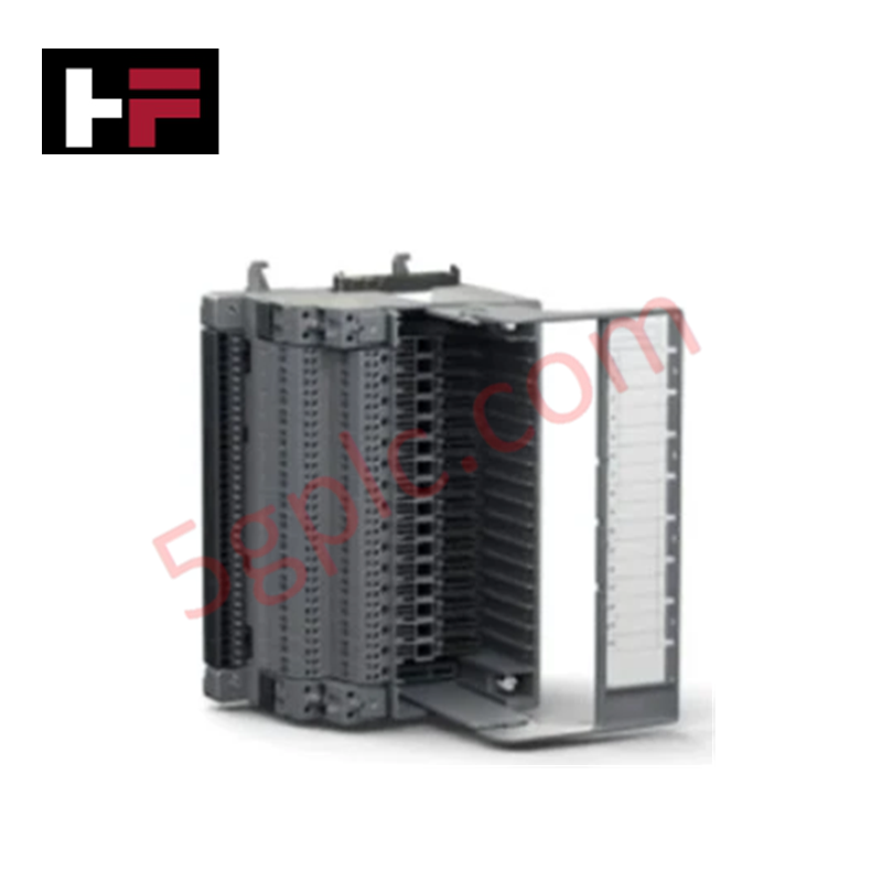
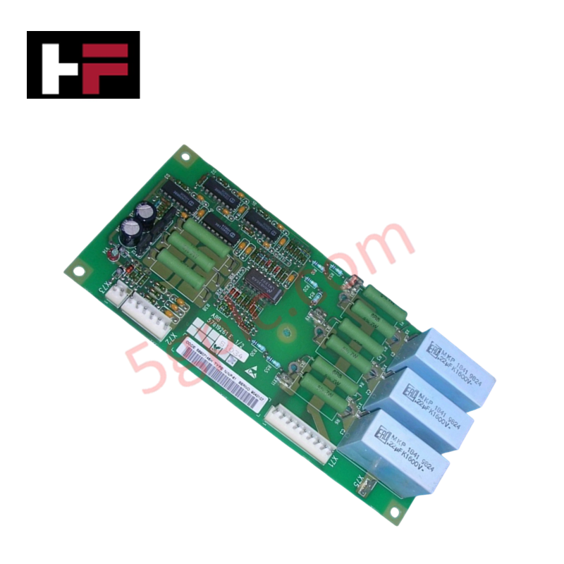
The ABB NIDI01, also cataloged as the NIDI01 Digital Input Termination Module, serves as the primary NIDI01 Digital Input Termination Module utilized to execute digital signal termination and conditioning across BAINET and Bailey Infi 90 / Network 90 platform networks.
Hardware Specifications
| Parameter | Specification |
|---|---|
| Model | NIDI01 |
| Brand | ABB |
| Origin | USA (Wickliffe, Ohio stock origin) |
| Weight | Standard termination module footprint |
| Dimensions | Standard Bailey Infi 90 termination block matrix |
| Operating Temp | 0 to 60 deg C |
| Power Consumption | Passive bus termination network architecture |
| Customs Tariff Code | 8537109150 |
Backplane Bus Communication Velocity and Signal Scaling
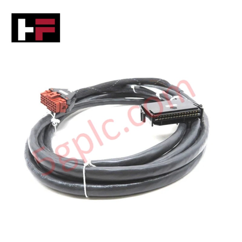
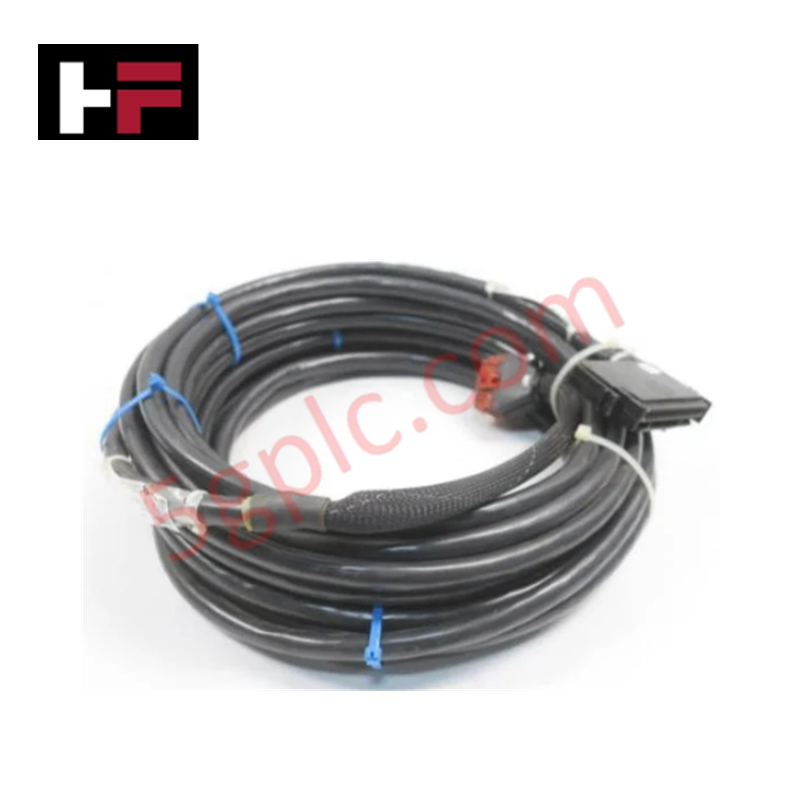
The ABB NIDI01 integrates directly with system termination cables to manage standard field inputs and routing mechanisms. The module features deterministic routing pathways to support backplane bus communication velocity and high-density I/O scaling across legacy and updated cabinet systems. By converting raw field wiring states into structured signals for the processing logic, it matches the operational requirements of Profinet / EtherNet/IP deterministic networks where bridging devices are deployed, sustaining firmware flash compatibility with upstream control units without introducing execution latency.
Frequently Asked Questions
Q: Does the NIDI01 module support live hot-swap replacement while the processing loop is live?
A: No, field power and ribbon cable connectivity must be completely isolated prior to mounting or unmounting the assembly to avoid field loop transients or damage to adjacent digital input cards.
Q: How should field input shielding be handled at the NIDI01 terminals?
A: All field signal shields must be collected and tied to a single, dedicated low-impedance master instrument ground bus in the cabinet enclosure to prevent ground loops.
Field Installation Guidelines
- Mount the module securely onto the specified cabinet termination rack or rail infrastructure to maintain physical chassis ground continuity.
- Route all incoming digital field lines cleanly through cable trays, keeping standard physical separation between low-voltage DC input logic lines and heavy AC power conductors.
- Terminate wires with appropriate field lugs, ensuring screw terminals are tight and secure to resist vibration-induced loosening over long-term operations.
- Verify overall cable routing layout parameters conform to standard industrial noise suppression and shielding guidelines before powering the local I/O cluster.
Additional Information
- 100% Genuine Parts: All products are original and authentic, ensuring reliable industrial performance.
- 30-Day Refund Guarantee: Return any in-stock item within 30 days in original, unopened packaging for a full refund (excluding shipping and fees).
- 12-Month Warranty: Covers defects in materials or workmanship; excludes misuse, normal wear, or unauthorized modifications.
- Worldwide Shipping: We ship via USPS, UPS, FedEx, and DHL. Delivery times vary by country and may be subject to customs or import fees.
- Support & Contact: Technical and warranty assistance is available anytime. Contact us here: Contact.
- Purchase Guidance: Check product specifications and compatibility carefully before ordering to ensure proper application.
Tech & Buying Guide
Industrial PC vs. Commercial PC: Selecting the Right Hardware for Automation
In the demanding world of factory automation, selecting the correct computing platform is critical for system reliability. While commercial PCs power our daily lives, they often fail when subjected to the harsh realities of the production floor. Understanding the fundamental differences between an Industrial PC (IPC) and a standard office PC helps engineers optimize control systems for longevity and performance.

Core Components of Programmable Logic Controllers (PLC) in Industrial Automation
A Programmable Logic Controller (PLC) serves as the digital backbone of modern factory automation. Whether you are managing complex assembly lines or simple process loops, understanding the hardware and software architecture of a PLC is essential for any control systems engineer.

PLC vs. PC: Navigating the Architectural Differences in Industrial Automation
In the realm of factory automation, professionals often debate the roles of Programmable Logic Controllers (PLCs) and Personal Computers (PCs). While both devices share fundamental computing architectures—including a processor, memory, and an operating system—their design philosophies diverge significantly. Understanding these distinctions is critical for selecting the right hardware for your industrial control systems.