










Product Details
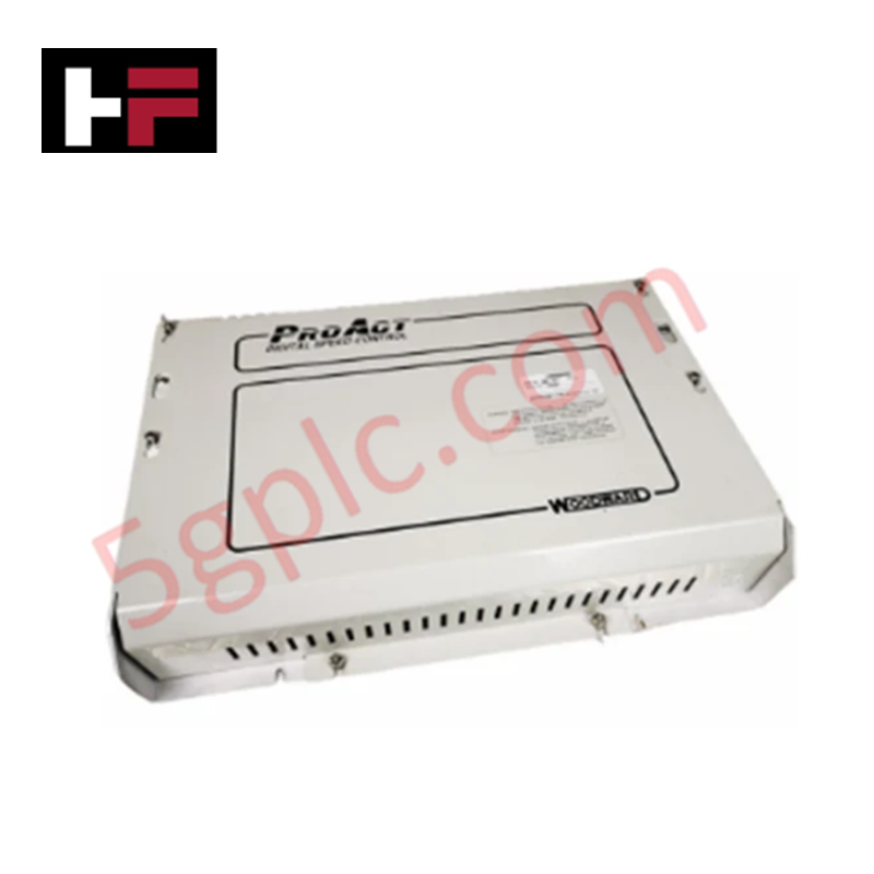
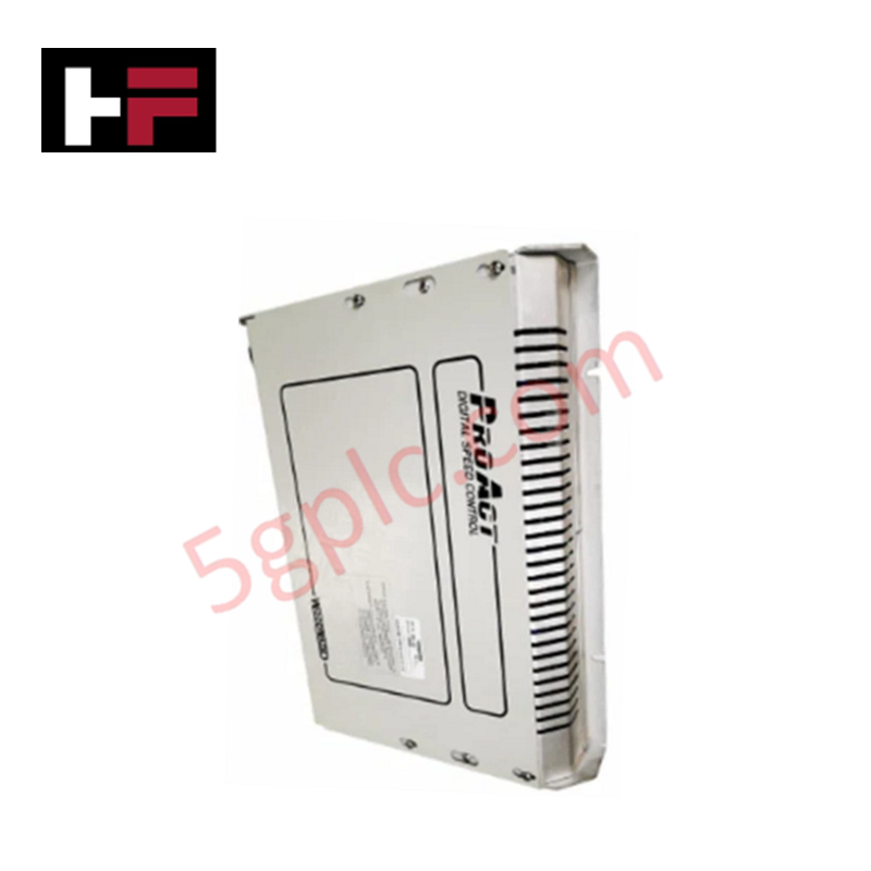
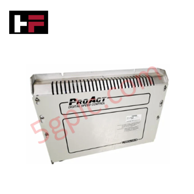
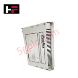
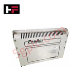
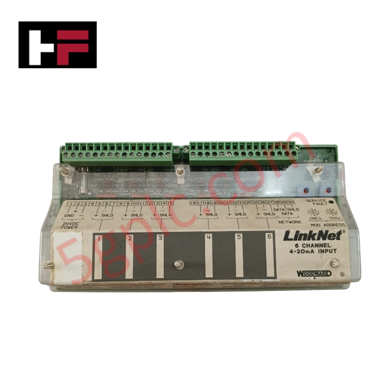
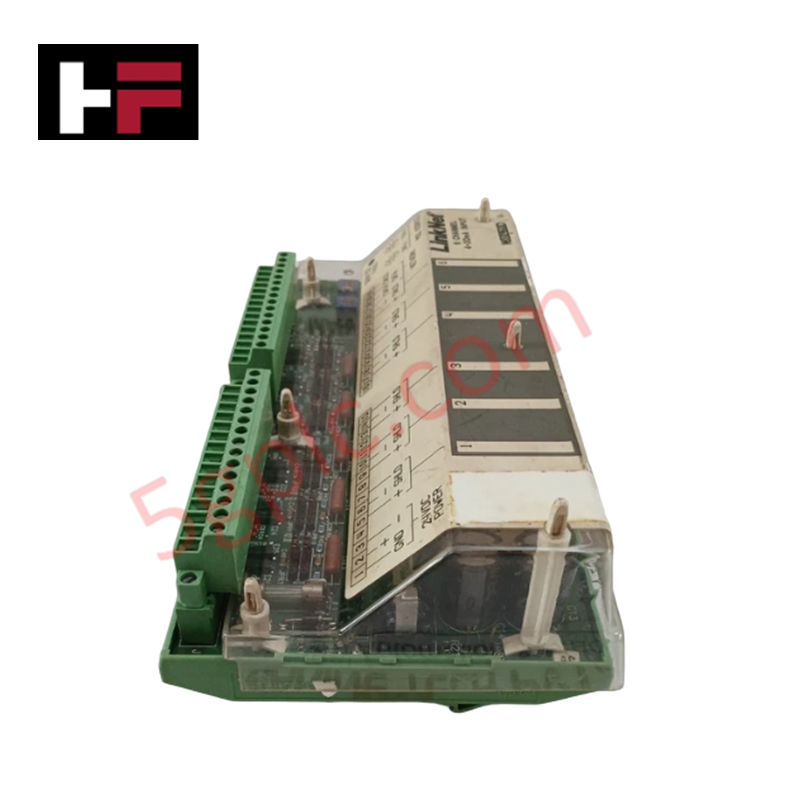
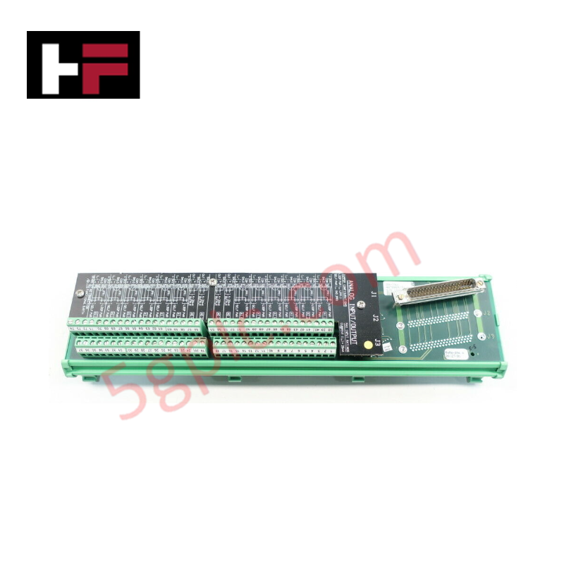
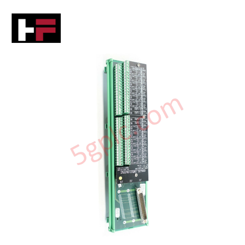
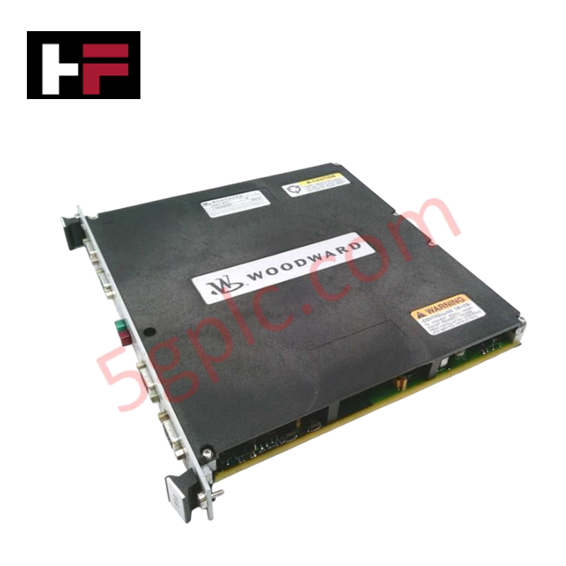
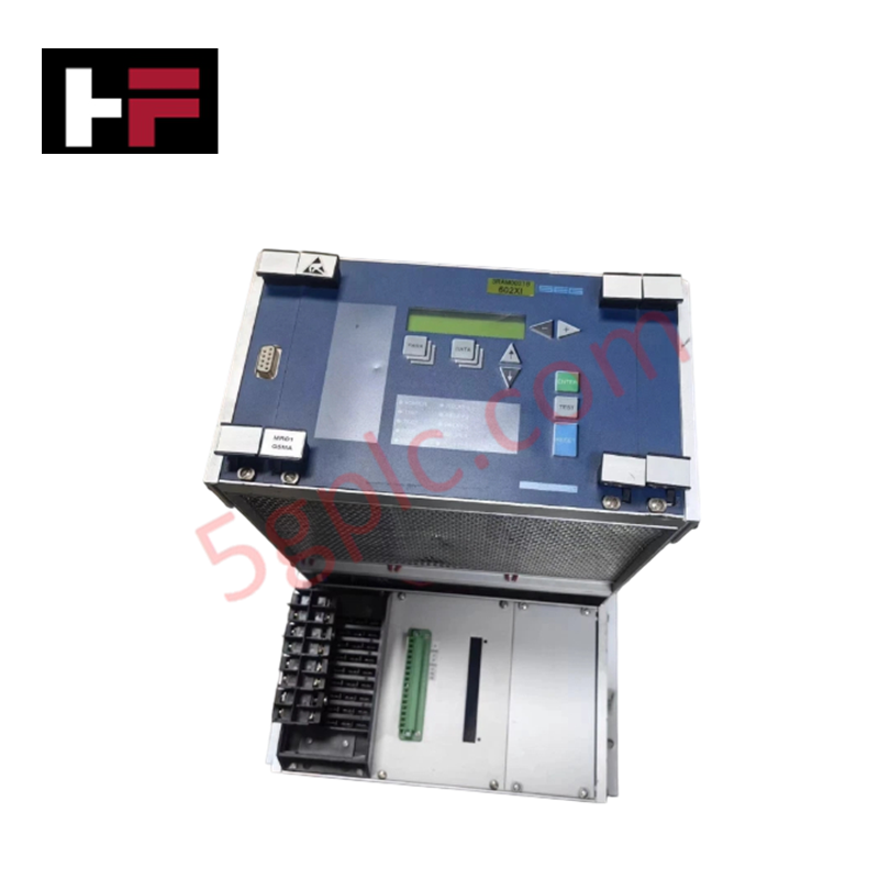
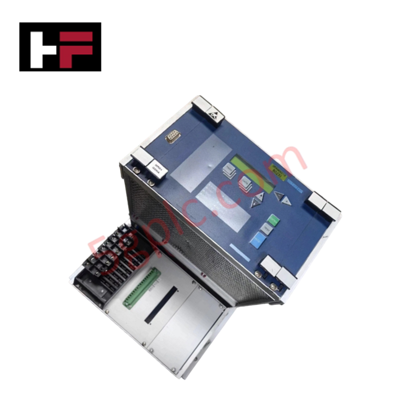
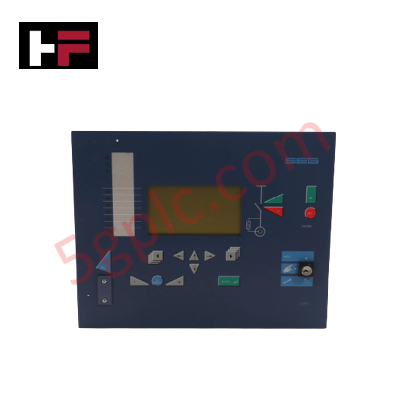
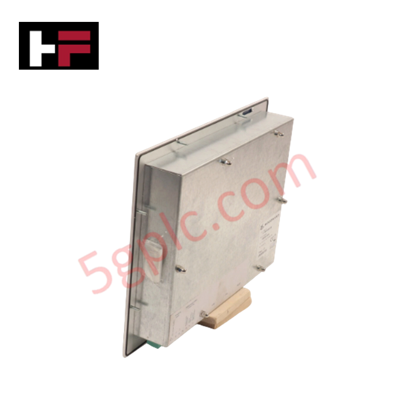
The Woodward 9905-463, also cataloged as the 9905-463 Digital Speed Control Module, operates as a dedicated hardware component for turbine rotational velocity regulation within engine management platforms.
Hardware Specifications
| Parameter | Specification |
|---|---|
| Model | 9905-463 |
| Brand | Woodward |
| Origin | Not specified |
| Weight | Approximately 1 kg |
| Input Voltage | 18-32 VDC |
| Output Voltage | 0-10 VDC |
| Current Range | 0-200 mA (Control Signal) |
Actuator Loop Feedback Response
The 9905-463 module regulates prime mover output by computing speed setpoints and transmitting control signals to the fuel actuator. To maintain a stable actuator loop feedback response, the digital controller continuously compares real-time speed input data against the load-sharing reference. The output stage provides up to 200 mA of control current, ensuring rapid response for valve positioning. The control algorithm incorporates internal compensation to mitigate mechanical hysteresis, providing precise load regulation and overspeed protection. Integration with external communication protocols allows for seamless data exchange, ensuring that setpoint adjustments are executed without introducing oscillations into the governor loop.
Frequently Asked Questions
Q: Does the module support hot-swapping functionality during operation?
A: No, the 9905-463 is not designed for hot-swapping. Ensure the 24 VDC power source is fully isolated from the terminal block before installation or removal to prevent electrical damage to the controller circuitry.
Q: How should the control output be wired to the actuator?
A: The 0-200 mA control signal should be routed using shielded twisted-pair cabling to minimize induced EMI. Ensure the actuator load resistance is compatible with the controller output voltage and current ranges to avoid saturation or signal clipping.
Field Installation Guidelines
- Mounting: Secure the controller within an industrial enclosure protected from moisture and particulate contamination. Ensure the mounting surface is rigid to minimize the impact of external vibrations on the internal processing components.
- Wiring: Route signal inputs (speed feedback) and output control lines away from high-current power cabling to prevent electromagnetic interference. Terminate all shields at the common cabinet ground stud.
- Power Connection: Verify that the supply voltage remains within the 18-32 VDC range. Utilize a dedicated power supply that is filtered to suppress noise generated by the engine starting system.
Additional Information
- 100% Genuine Parts: All products are original and authentic, ensuring reliable industrial performance.
- 30-Day Refund Guarantee: Return any in-stock item within 30 days in original, unopened packaging for a full refund (excluding shipping and fees).
- 12-Month Warranty: Covers defects in materials or workmanship; excludes misuse, normal wear, or unauthorized modifications.
- Worldwide Shipping: We ship via USPS, UPS, FedEx, and DHL. Delivery times vary by country and may be subject to customs or import fees.
- Support & Contact: Technical and warranty assistance is available anytime. Contact us here: Contact.
- Purchase Guidance: Check product specifications and compatibility carefully before ordering to ensure proper application.
Tech & Buying Guide

Spatial Computing in Industrial Automation: Elevating PLC and DCS Operations with AR and VR
Industry 4.0 integrates digital intelligence into field operations, transforming factory automation landscapes worldwide. Spatial technologies—specifically Augmented Reality (AR) and Virtual Reality (VR)—redefine how engineers interact with industrial control systems. By bridging computer-generated CAD models with real-time operational technology (OT) data, immersive displays enable intuitive monitoring, rapid diagnostics, and safer maintenance across complex processing facilities.

Master Acceptance Testing: Understanding FAT and SAT in Industrial Control Systems
Factory Acceptance Testing (FAT) and Site Acceptance Testing (SAT) serve as critical quality assurance gateways in complex industrial control systems. Both procedures verify that programmable logic controllers (PLCs), distributed control systems (DCS), and associated field devices meet strict functional specifications. However, executing these tests effectively requires clear delineation between off-site staging and final field commissioning.

Industrial Networking Essentials: Demystifying Hubs, Switches, and Routers in Control Systems
Industrial automation relies heavily on robust networking infrastructure to connect programmable logic controllers (PLCs), distributed control systems (DCS), and human-machine interfaces (HMIs). Modern factory automation environments generate vast amounts of real-time operational data across deterministic networks. Understanding the structural differences between hubs, switches, and routers ensures optimal traffic segmentation, minimizes latency, and maintains high network availability.