










Product Details
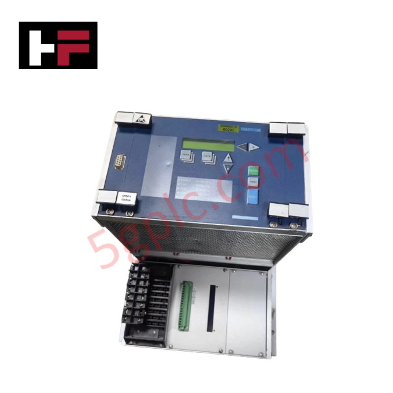
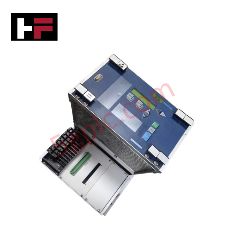
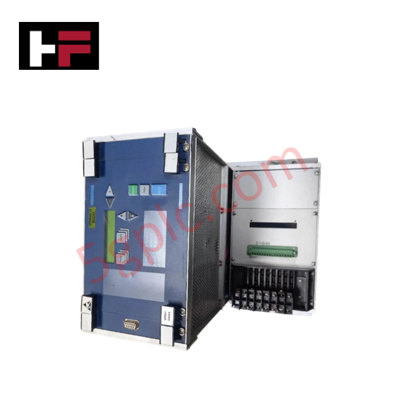
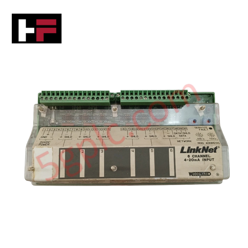
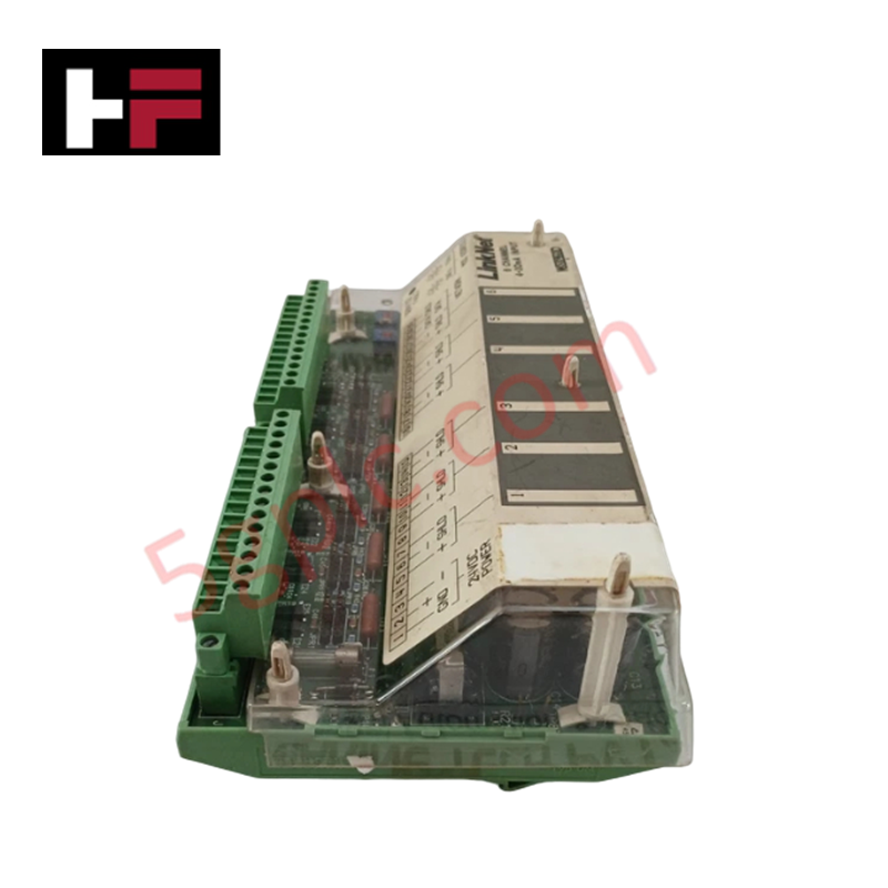
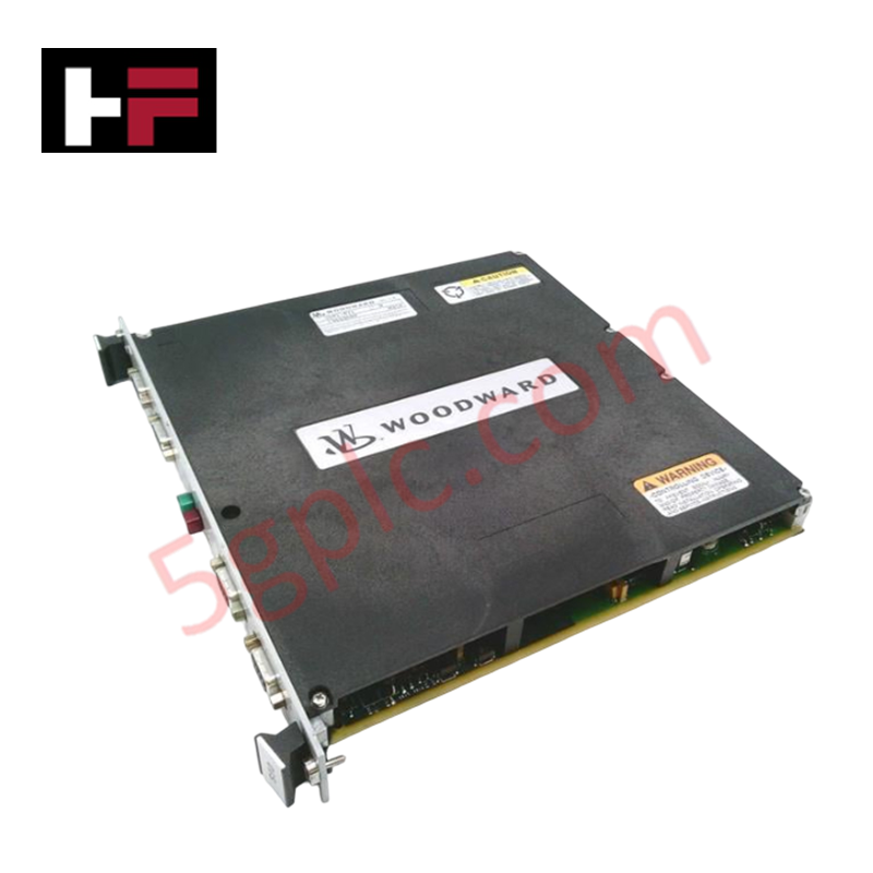
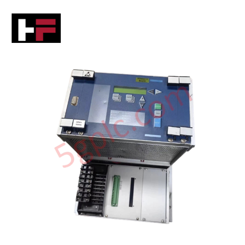
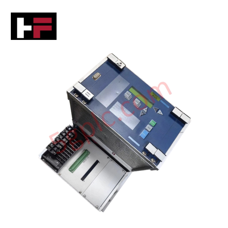
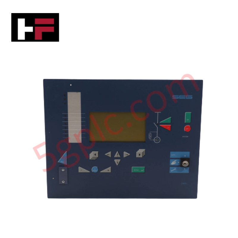
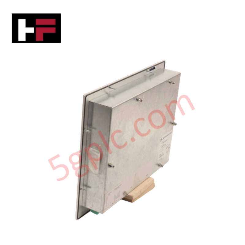
The Woodward MRD1T2HTL6M42, also cataloged as the MRD1T2HTL6M42 Digital Speed Control Module, operates as a dedicated hardware component for closed-loop engine speed governing and speed signal processing within industrial control systems. Powered by a 24 VDC input with a 10 W power consumption, the module exchanges realtime parameters over 2x Ethernet, 1x RS232, and 1x RS485 communication ports. The hardware is housed in a 273.6 mm x 214.1 mm x 59.2 mm enclosure weighing 1.5 kg, executing continuous signal calculations across operating temperatures ranging from -40 deg C to +70 deg C.
Hardware Specifications
| Parameter | Specification |
|---|---|
| Model | MRD1T2HTL6M42 |
| Brand | Woodward |
| Origin | USA |
| Weight | 1.5 kg |
| Dimensions | 273.6 mm x 214.1 mm x 59.2 mm |
| Operating Temp | -40 deg C to +70 deg C |
| Power Consumption | 10 W (24 VDC Input Voltage) |
| Communication Ports | 2x Ethernet, 1x RS232, 1x RS485 |
| Product Type | Digital Speed Control Module |
Actuator Loop Feedback Response
The Woodward MRD1T2HTL6M42 digital speed control module incorporates closed-loop algorithms designed to stabilize actuator loop feedback response during dynamic speed demands. High-speed input channels continuously process speed sensor pulses, generating corrected actuator command outputs with minimal phase delay. Communication streams active across the dual Ethernet, RS232, and RS485 serial interfaces operate independently of internal governing execution cycles, preventing control loop latency and eliminating transient speed hunting under step-load changes.
Frequently Asked Questions
Q: What power wiring guidelines must be observed when supplying 24 VDC to the module terminal block?
A: Connect the 24 VDC power feed using dedicated stranded copper conductors sized appropriately to minimize line voltage drop. Ensure correct polarity alignment at the power terminals prior to energizing, and install an external fast-acting inline fuse to protect internal board circuitry from overcurrent events.
Q: How should communication cable shielding be terminated across the Ethernet, RS232, and RS485 ports?
A: Shielded twisted-pair cables are required for all serial and network communication links. Terminate cable shields directly to the cabinet ground bus at a single point to prevent ground loop currents from interfering with data transmission across the RS232 and RS485 lines.
Field Installation Guidelines
Mount the module securely inside an IP-rated industrial panel enclosure using appropriate mounting hardware, maintaining structural stability against machine vibration. Ensure adequate physical clearance surrounding the housing to allow natural air convection across the enclosure surface for heat dissipation. Route low-level speed sensor wiring and communication lines in dedicated wire raceways separated from 24 VDC power circuits and high-voltage AC conductors. Bond the protective chassis grounding connection to the central enclosure earth ground bar via a short, low-impedance copper grounding wire prior to initial power-up.
Additional Information
- 100% Genuine Parts: All products are original and authentic, ensuring reliable industrial performance.
- 30-Day Refund Guarantee: Return any in-stock item within 30 days in original, unopened packaging for a full refund (excluding shipping and fees).
- 12-Month Warranty: Covers defects in materials or workmanship; excludes misuse, normal wear, or unauthorized modifications.
- Worldwide Shipping: We ship via USPS, UPS, FedEx, and DHL. Delivery times vary by country and may be subject to customs or import fees.
- Support & Contact: Technical and warranty assistance is available anytime. Contact us here: Contact.
- Purchase Guidance: Check product specifications and compatibility carefully before ordering to ensure proper application.
Tech & Buying Guide

Why Programmable Logic Controllers Drop into Stop Mode: An Expert Analysis
Industrial automation systems rely heavily on Programmable Logic Controllers (PLCs) to maintain uninterrupted production. When a PLC unexpectedly shifts from Run to Stop mode, whole manufacturing lines stall.
As control systems evolve across modern factory automation, understanding the root causes of these interruptions helps engineers minimize costly downtime. This technical guide breaks down why PLCs trip into Stop mode and provides practical strategies to mitigate system faults.

Understanding Root Causes of Unplanned PLC Stop Mode in Industrial Automation
Modern Programmable Logic Controllers manage execution through distinct operational states: Run, Stop, Start-Up, and Hold. During power-up, a controller initializes memory registers within Stop mode before briefly transitioning to Start-Up mode. During this phase, internal self-diagnostics evaluate system integrity across hardware and user programs. If the controller detects no critical faults, it enters Run mode to execute the control program continuously. However, any severe system anomaly forces the CPU back into Stop mode immediately to prevent erratic machine behavior across the plant floor.

Human-Machine Interface Design: Essential Guide to HMI Selection, Visualization, and Control System Integration
Human-Machine Interfaces (HMIs) serve as the primary operational window into complex industrial automation systems. Modern HMIs convert raw machine data into clear graphical displays, enabling operators to oversee entire manufacturing processes in real time. Instead of relying on physical control panels full of hardwired switches, engineers program interactive screens using intuitive graphics, dynamic color coding, and responsive touch interfaces. Over my 15 years in control systems engineering, I have observed HMIs transform from basic display screens into sophisticated command centers that drive operational efficiency across DCS and PLC environments.