










Product Details
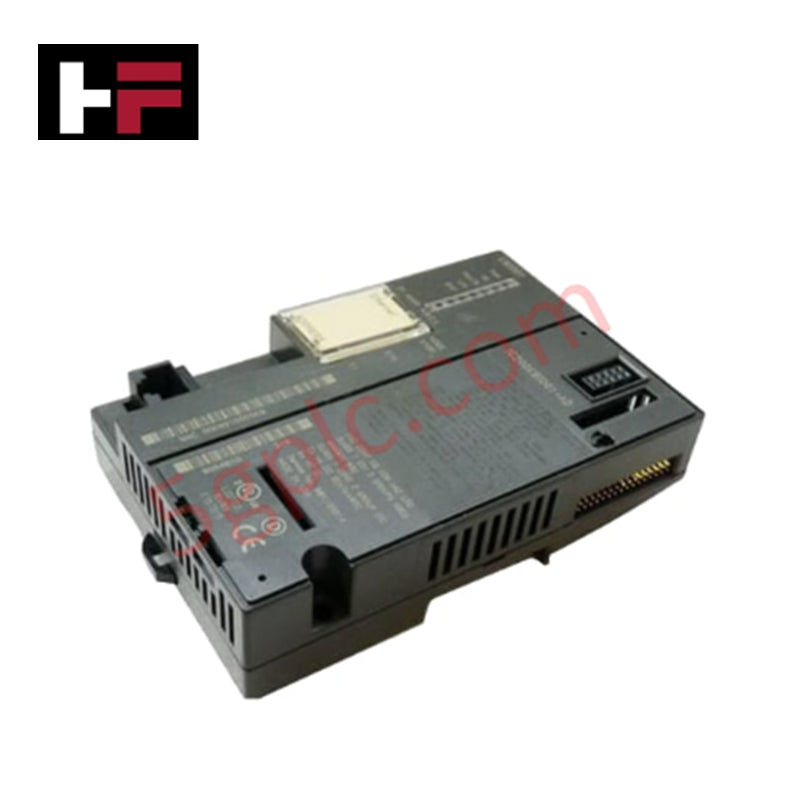
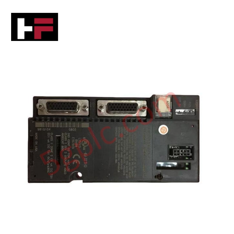
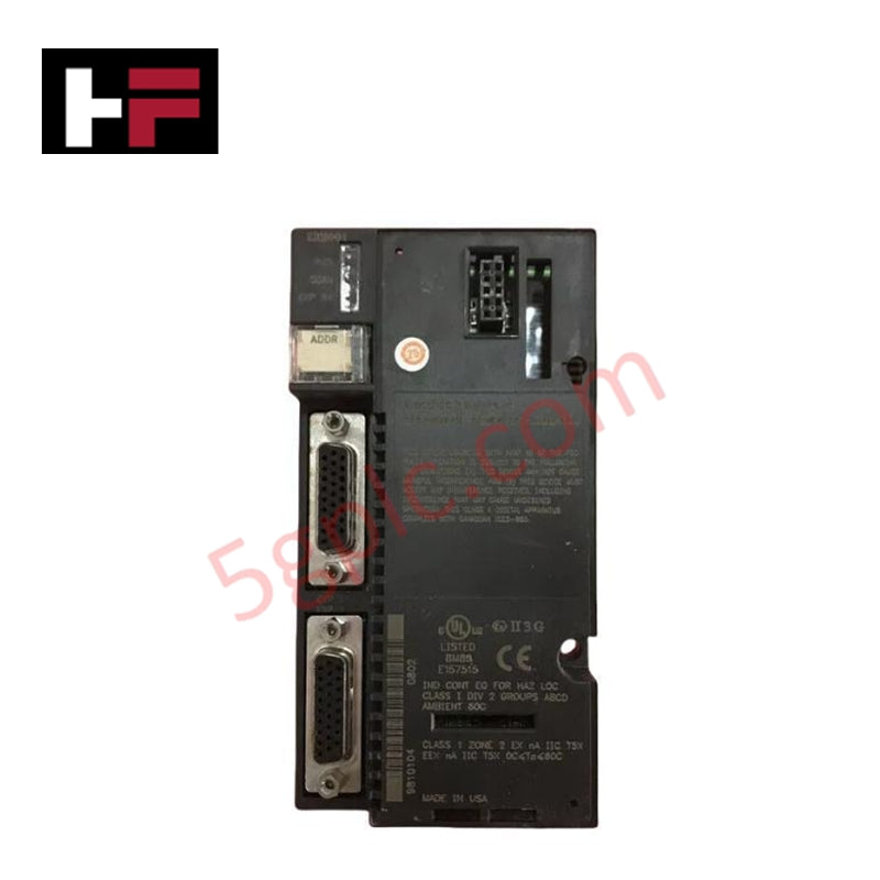
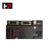
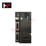
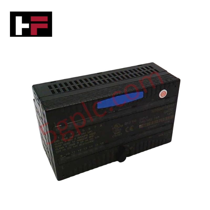
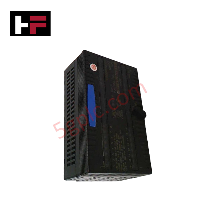
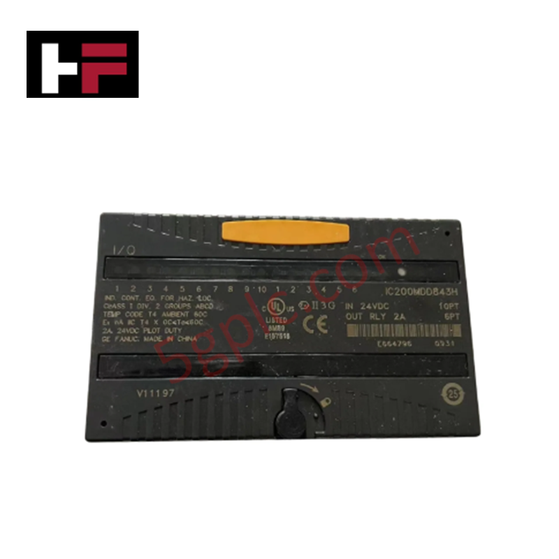
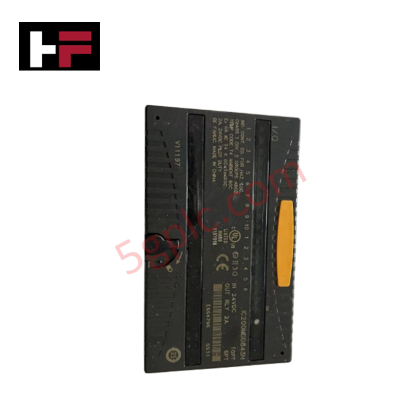
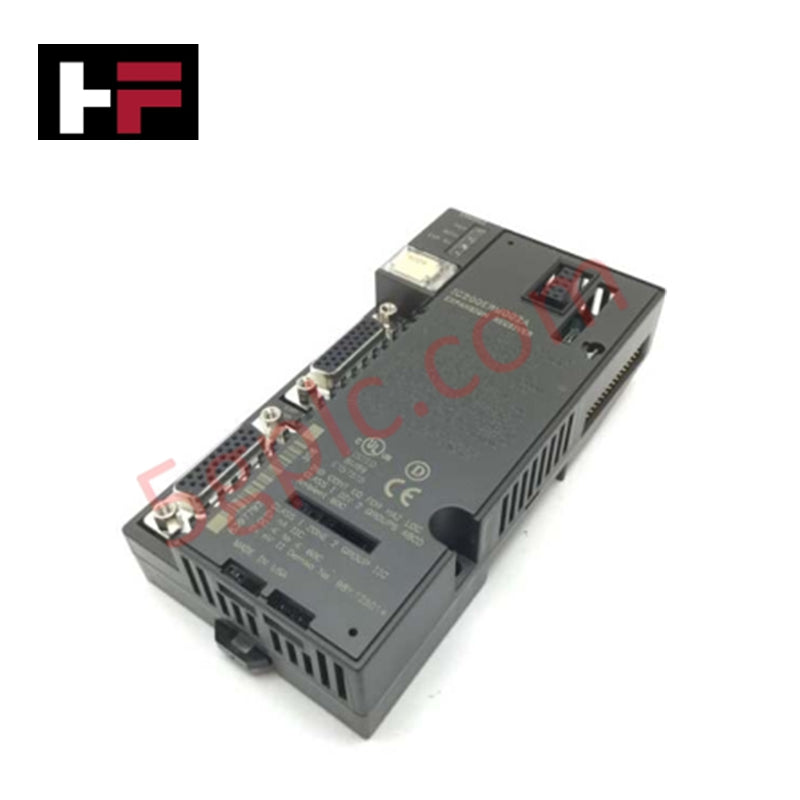
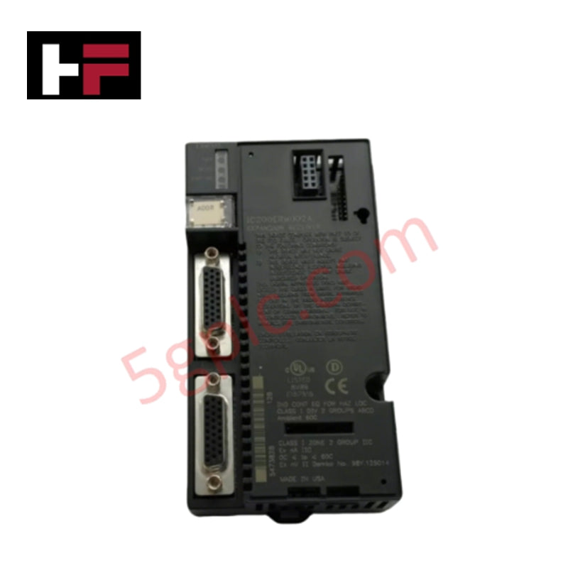
The GE IC200ERM001C, also cataloged as the IC200ERM001 Isolated Expansion Receiver Module, operates as a dedicated hardware component for multi-rack I/O bus expansion and signal isolation within GE VersaMax control platforms.
Hardware Specifications
| Parameter | Specification |
|---|---|
| Model | IC200ERM001C |
| Brand | GE (GE Fanuc / Emerson) |
| Origin | USA |
| Weight | 0.23 kg (0.50 lbs) |
| Power Consumption | Power sourced via backplane power supply |
| Max Backplane Output Voltage | 5 VDC |
| Min Backplane Output Voltage | 3.3 VDC |
| Expansion Connectors | 2 female 26-pin D-shell ports |
| Rack ID Selection | Onboard rotary switch |
| Status Indicators | LEDs for Power Status and Expansion Bus Status |
| Mounting Location | Far-left slot on VersaMax expansion rack DIN rail |
Backplane Bus Communication Velocity & Deterministic Network Execution
The IC200ERM001C receives isolated expansion bus signals from an upstream expansion transmitter module (such as the ETM001) via its top 26-pin D-shell port. It rebuilds and routes local backplane voltage levels between 3.3 VDC and 5 VDC to power downstream I/O and communication modules installed on the expansion rack, optimizing backplane bus communication velocity across long distances.
The bottom female 26-pin D-shell port enables daisy-chain connections to subsequent expansion racks or accommodates an expansion bus terminator plug on the final node. Full integration into Profinet / EtherNet/IP deterministic network topologies is maintained through the primary controller interface, while strict firmware flash compatibility ensures synchronized scan execution and low-latency protocol passthrough across all extended racks.
Frequently Asked Questions
Q: What is the functional role of the rotary switch located on the IC200ERM001C module?
A: The rotary switch located under the front access door sets the unique hardware address (Rack ID) for the specific expansion rack within the system topology.
Q: How are the two 26-pin female D-shell ports utilized on the expansion receiver module?
A: The top D-shell port receives the expansion cable from the upstream transmitter or preceding receiver, while the bottom port daisy-chains to the next expansion rack or houses a bus termination plug on the final rack.
Q: Can the IC200ERM001C module be removed or inserted while the expansion rack power supply is energized?
A: No. All incoming power sources to the expansion rack and primary controller must be de-energized prior to removing or installing the module to prevent electrical damage to the expansion bus.
Field Installation Guidelines
- Power Shutdown: De-energize and lock out all power sources feeding the host system and the expansion rack backplane prior to installation or maintenance.
- Rack Position: Mount the IC200ERM001C module exclusively in the far-left slot position of the VersaMax expansion rack on the 35 mm DIN rail.
- Address Configuration: Set the onboard rotary switch to the assigned expansion rack ID number prior to securing the module onto the backplane carrier.
- Cable Interconnection: Secure the 26-pin expansion cable from the upstream transmitter into the top D-shell port using integrated thumbscrews. Attach a daisy-chain cable or terminal plug to the bottom D-shell port.
- Electrostatic Discharge (ESD): Wear a grounded anti-static wrist strap attached to the enclosure metallic earth during installation to protect onboard IC logic from static damage.
Additional Information
- 100% Genuine Parts: All products are original and authentic, ensuring reliable industrial performance.
- 30-Day Refund Guarantee: Return any in-stock item within 30 days in original, unopened packaging for a full refund (excluding shipping and fees).
- 12-Month Warranty: Covers defects in materials or workmanship; excludes misuse, normal wear, or unauthorized modifications.
- Worldwide Shipping: We ship via USPS, UPS, FedEx, and DHL. Delivery times vary by country and may be subject to customs or import fees.
- Support & Contact: Technical and warranty assistance is available anytime. Contact us here: Contact.
- Purchase Guidance: Check product specifications and compatibility carefully before ordering to ensure proper application.
Tech & Buying Guide

Top 5 Operational Advantages of HMIs in Modern Factory Automation

Importance of Safety Barriers in PLC and DCS Control Systems
