










Product Details
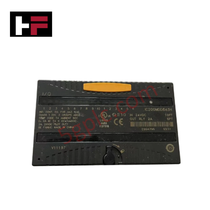
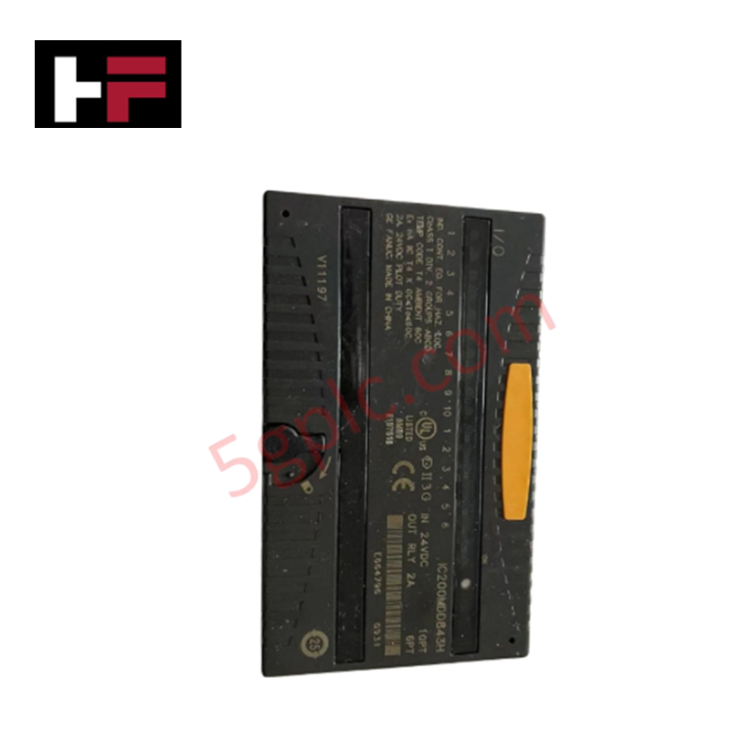
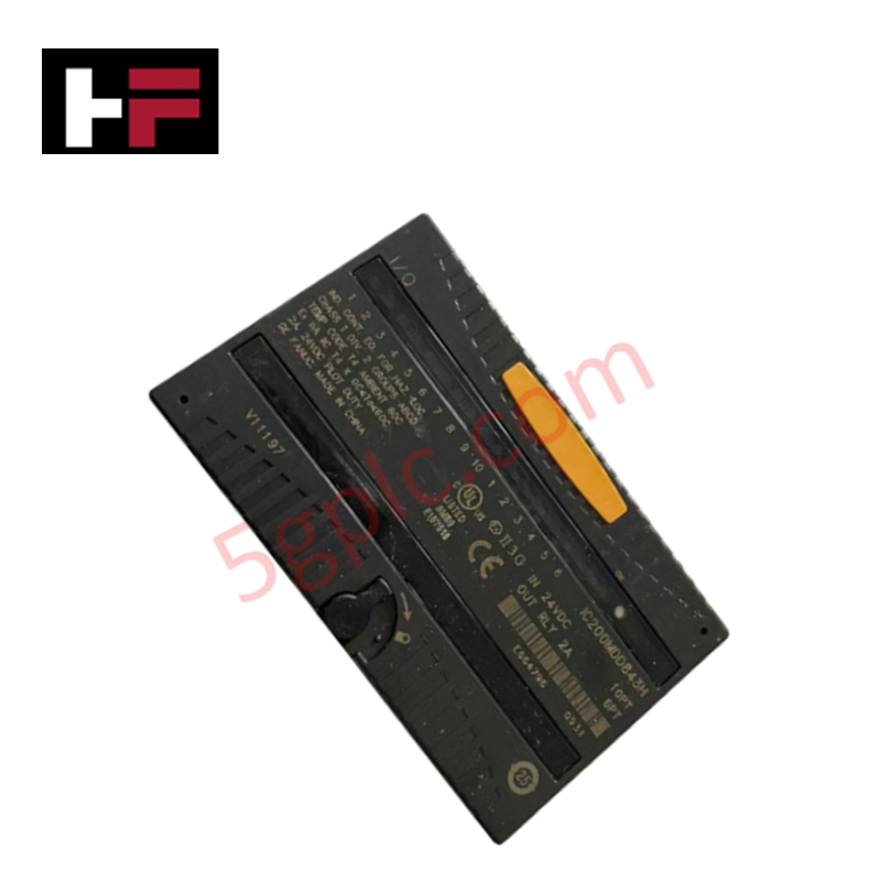
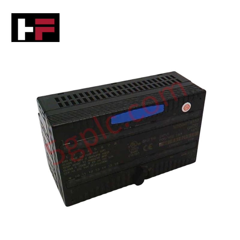
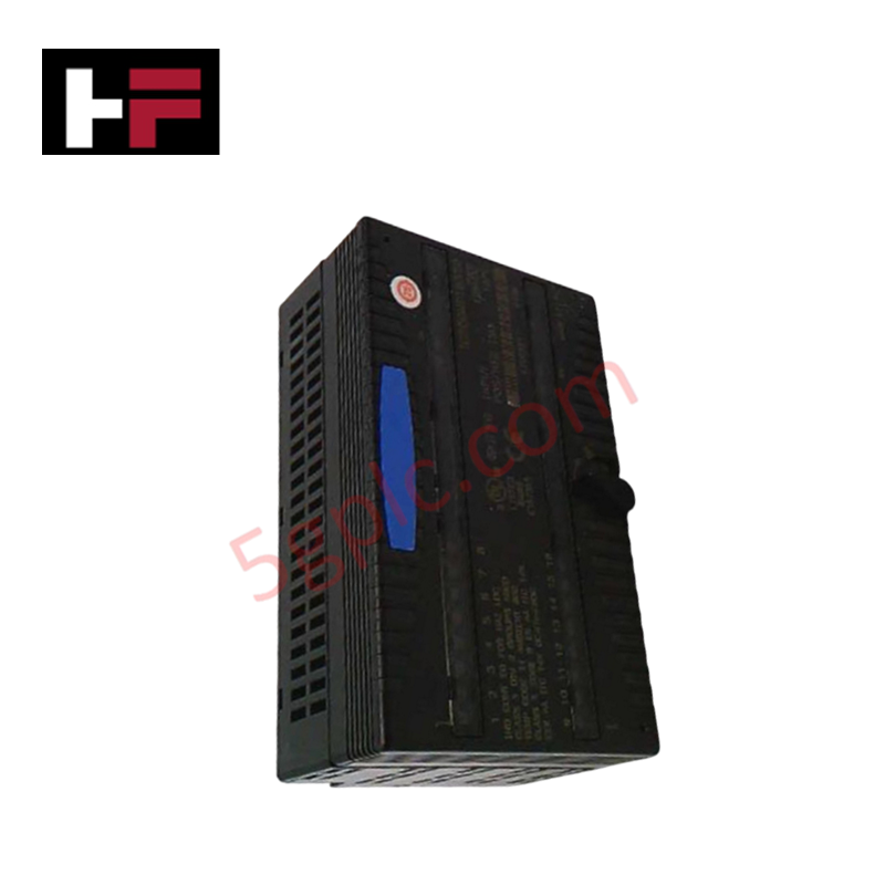
The GE IC200MDD843E, also cataloged as the IC200MDD843 Discrete Mixed Module, operates as a dedicated hardware component for discrete signal switching and relay output execution within GE VersaMax control networks.
Hardware Specifications
| Parameter | Specification |
|---|---|
| Model | IC200MDD843E |
| Brand | GE (GE Fanuc / Emerson) |
| Origin | USA |
| Weight | 0.23 kg (0.50 lbs) |
| Dimensions | 4.3 in x 1.956 in x 2.63 in (excluding carrier and connectors) |
| Operating Temp | Standard industrial operating range |
| Power Consumption | Rack-mounted backplane power; up to 190 mA backplane current draw |
| Total I/O Points | 16 points (10 inputs, 6 outputs) |
| Input Type | Positive logic / sourcing inputs |
| Output Type | Fixed coil relays with moving armature and silver alloy contacts |
| Output Current Rating | Up to 8 A total output current |
| Maximum Response Speed | 10 ms |
| Switching Frequency | Maximum 20 cycles per minute with inductive load |
| Terminal Interface | 18 Type A field wiring terminals; additional Type B via shorting bar |
| Internal Protection | No internal fuses or snubber circuits; no channel-to-channel isolation |
Suffix Breakdown & Model Matrix
| Base Model | Suffix Revision | Hardware Description |
|---|---|---|
| IC200MDD843 | A / B / C / D | Early hardware revisions of 16-point discrete mixed module |
| IC200MDD843 | E | Updated revision with enhanced component tolerance and manufacturing lifecycle updates |
Backplane Bus Communication Velocity & Deterministic Network Execution
The IC200MDD843E module routes discrete field signals directly across the VersaMax backplane, drawing up to 190 mA from the backplane rail based on active input and relay coil states. The internal bus architecture provides predictable signal transfer to maintain high backplane bus communication velocity across local and expansion racks.
Full compatibility with Profinet / EtherNet/IP deterministic networks via VersaMax network interface modules ensures deterministic scan times and low-latency digital update rates. Integrated board firmware maintains strict firmware flash compatibility across controller revisions, permitting flexible I/O density scaling across high-density mixed field points without processing delay.
Frequently Asked Questions
Q: What are the current draw and power source requirements for the IC200MDD843E module?
A: Logic circuits draw up to 190 mA from the rack backplane supply depending on active I/O count, while field loads require an external power source connected to the module terminal block.
Q: Does the IC200MDD843E feature onboard fuses, snubbers, or channel isolation?
A: No. The module does not contain internal snubbers, onboard fuses, or channel-to-channel isolation. External suppression and fusing must be installed on field wiring loops.
Q: What contact rating and response speed apply to the 6 relay output points?
A: The outputs use silver alloy relay contacts rated for up to 8 A total current capacity, with a maximum response speed of 10 ms and a maximum switching rate of 20 cycles per minute under inductive loads.
Field Installation Guidelines
- Power Isolation: Disconnect primary rack backplane power and external 24 VDC/120 VAC field power before mounting or removing the module from its carrier base.
- Carrier Mounting: Align the module side slots with the VersaMax carrier board tracks and press firmly down until the latch mechanism locks into position.
- Field Wiring: Connect positive logic sourcing inputs and relay output load lines to the 18 Type A terminals. Install external fuse links on each output channel to protect relay contacts.
- Inductive Suppression: Install external RC snubbers or flyback diodes across external inductive loads to prevent contact arcing and voltage transient reflection back to the module.
- Electrostatic Protection: Wear a grounded anti-static wrist strap connected to an unpainted metal frame point when setting up field wiring or handling unshielded hardware.
Additional Information
- 100% Genuine Parts: All products are original and authentic, ensuring reliable industrial performance.
- 30-Day Refund Guarantee: Return any in-stock item within 30 days in original, unopened packaging for a full refund (excluding shipping and fees).
- 12-Month Warranty: Covers defects in materials or workmanship; excludes misuse, normal wear, or unauthorized modifications.
- Worldwide Shipping: We ship via USPS, UPS, FedEx, and DHL. Delivery times vary by country and may be subject to customs or import fees.
- Support & Contact: Technical and warranty assistance is available anytime. Contact us here: Contact.
- Purchase Guidance: Check product specifications and compatibility carefully before ordering to ensure proper application.
Tech & Buying Guide

Top 5 Operational Advantages of HMIs in Modern Factory Automation

Importance of Safety Barriers in PLC and DCS Control Systems
