


Product Details
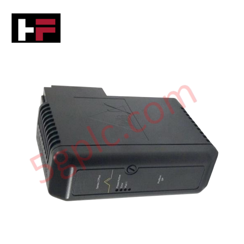
The Emerson KL4104X1-BA1 serves as the primary KL4104X1-BA1 Dual Universal Carrier utilized to execute physical module interfacing and redundant power routing across DeltaV hardware networks. This backplane unit accepts dual logic cards, routing redundant external operational line voltages and internal tracking registers over centralized trace matrices to prevent data drops during individual slot component failures.
Hardware Specifications
| Parameter | Specification |
| Model | KL4104X1-BA1 |
| Brand | Emerson |
| Origin | USA |
| Weight | 0.85 kg |
| Dimensions | Standard DeltaV dual-slot baseplate footprint |
| Operating Temp | -40 deg C to +70 deg C |
| Power Consumption | Redundant input power: +24 VDC at 1 A |
| Battery Power Path | +5.0 to +12.6 VDC at 1 mA for static register preservation |
| Slot Density | Dual universal module interface positions |
| Shock Resistance | 10g 1/2 sine wave for 11 ms |
| Vibration Resistance | 1 mm peak-to-peak from 2 to 13.2 Hz; 0.7g from 13.2 to 150 Hz |
| Airborne Contaminants | ISA-S71.04-1985 Class G3 compliance |
| Relative Humidity | 5% to 95% non-condensing |
Process Loop Routing and Channel-to-Channel Isolation
Mechanical execution of this dual universal carrier utilizes segregated multi-layer circuit boards to maintain system communication rates. The baseboard topology layout coordinates continuous channel-to-channel isolation matrices across the mapped I/O traces, checking that physical loop interfaces comply with the 4-20 mA HART loop protocol layer. This architecture isolates independent loop channels, preventing field-side voltage fluctuations, cross-talk anomalies, or transient ground loops from corrupting parallel bus registers or degrading data processing logic.
Frequently Asked Questions
Q: Does this carrier support the live insertion and removal of modules while backplane power remains active?
A: Yes. The hardware configuration handles active hot-swap module replacement. Operators can remove or insert a single card into a slot without causing voltage drops on the redundant power rail or disrupting active communication across the remaining operational module.
Q: What is the purpose of the continuous secondary battery power circuit on this carrier board?
A: The independent +5.0 to +12.6 VDC path routes a 1 mA current from auxiliary battery cells to maintain volatile internal memory structures, checking that configuration and tracking registers are preserved during primary +24 VDC supply failures.
Field Installation Guidelines
-
Chassis Rail Base Alignment: Position the dual carrier base housing directly over the designated industrial horizontal DIN-rail. Press down evenly until the mechanical grounding clips lock onto the metal rail structure to verify electrical continuity.
-
Redundant Power Conductor Securement: Connect the primary and secondary +24 VDC line leads into independent terminal clamps. Tighten all compression screws to factory torque specs to eliminate localized high-resistance terminal points.
-
Instrumentation Shield Drainage: Terminate all incoming external data loop screens and field wire shields at the master control cabinet common earth bus bar. Single-point grounding layouts suppress common-mode electromagnetic noise.
-
Corrosive Gas Isolation: In facilities with high ambient chemical pollution profiles matching Class G3 indexes, house the carrier assembly inside an airtight, positive-pressure enclosure to stop trace oxidation on the backplane connector pins.
Additional Information
- 100% Genuine Parts: All products are original and authentic, ensuring reliable industrial performance.
- 30-Day Refund Guarantee: Return any in-stock item within 30 days in original, unopened packaging for a full refund (excluding shipping and fees).
- 12-Month Warranty: Covers defects in materials or workmanship; excludes misuse, normal wear, or unauthorized modifications.
- Worldwide Shipping: We ship via USPS, UPS, FedEx, and DHL. Delivery times vary by country and may be subject to customs or import fees.
- Support & Contact: Technical and warranty assistance is available anytime. Contact us here: Contact.
- Purchase Guidance: Check product specifications and compatibility carefully before ordering to ensure proper application.


Tech & Buying Guide

Why 24V DC Power Supplies Standardize Modern Industrial Automation
Industrial control cabinets worldwide rely on 24V DC as the universal power standard for field instrumentation, sensors, and controllers. Walk into any manufacturing plant, and you will find PLCs, human-machine interfaces (HMIs), and smart actuators running on extra-low voltage DC. Standardizing on 24V DC enhances operational safety, lowers cabinet footprint, and maintains steady control performance across factory networks.

Essential Motion Control Commands: A Practical Guide for Engineers
Automation engineers often rely on precise position and speed control to drive modern factory machinery. Modern industrial systems, such as Programmable Logic Controllers (PLCs) and Distributed Control Systems (DCS), depend heavily on standardized motion instructions. Mastering these commands ensures operational safety, protects mechanical components, and optimizes cycle times across production lines.

Mastering Modern Industrial Joystick Controls in Heavy Automation
Industrial joysticks play a pivotal role in human-machine interaction across heavy material handling and mobile hydraulics. These tactile controllers translate complex operator movements into precise electrical signals for PLCs, motion controllers, and DCS networks. Consequently, selecting and installing the right joystick architecture ensures operator safety, reduces fatigue, and optimizes equipment performance.