










Product Details
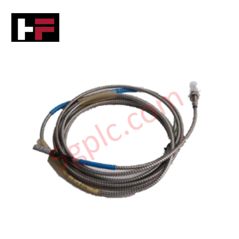
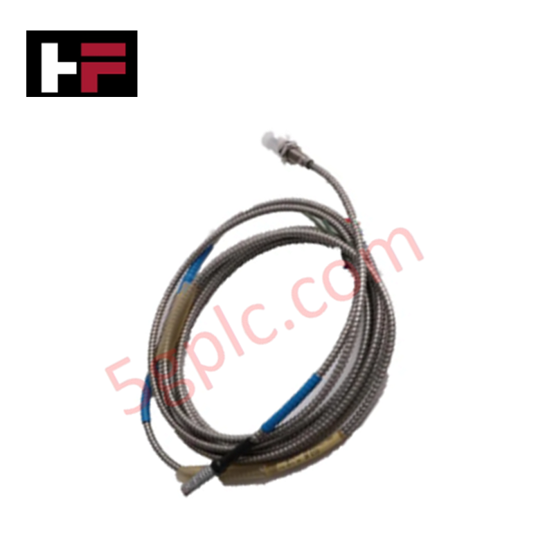
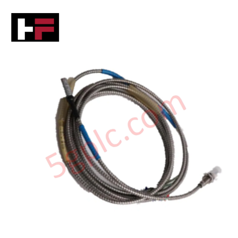
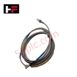
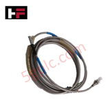
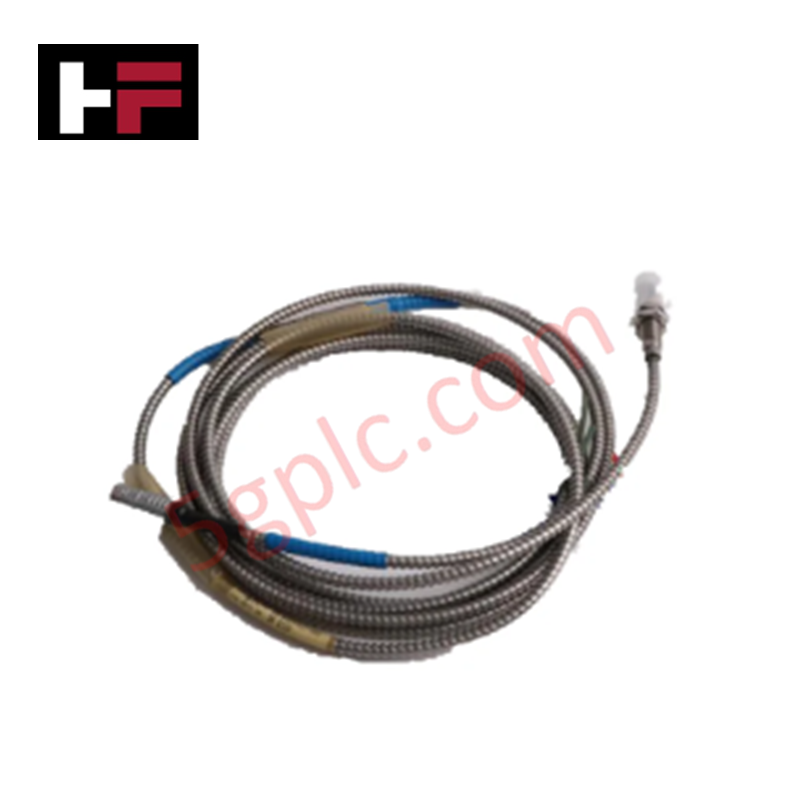
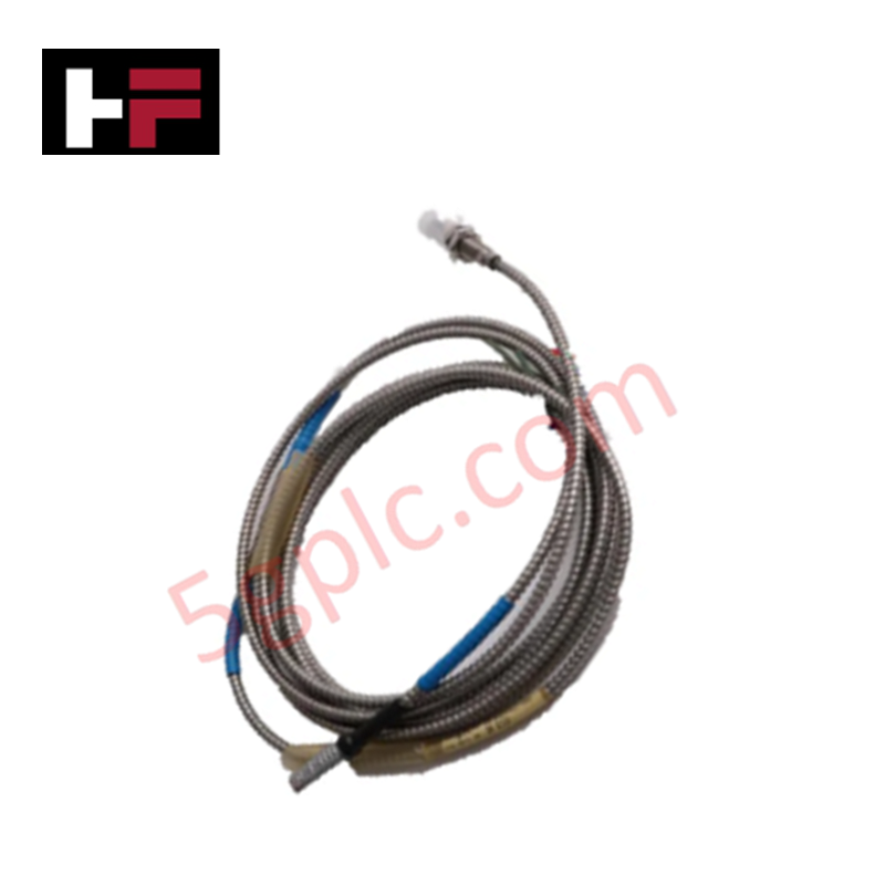
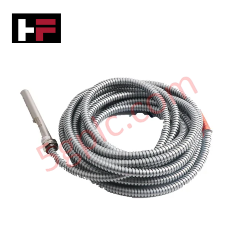
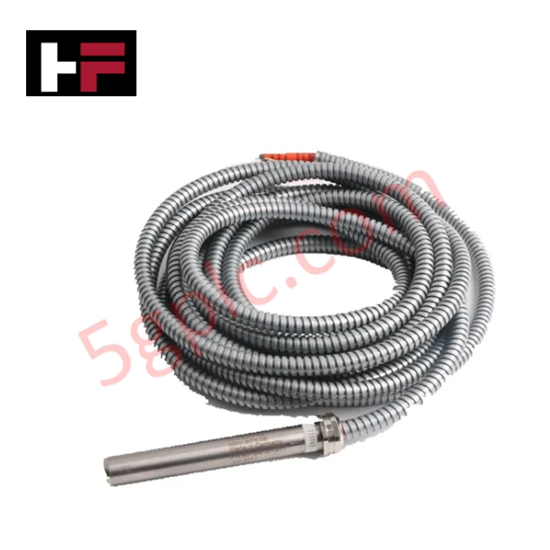
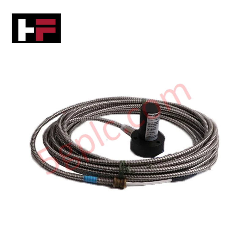
Configured for non-contact shaft displacement monitoring, the Epro PR6453/240-101 (PR6453/240-101) Eddy Current Sensor Probe provides direct physical execution of proximity detection for rotating machinery.
Hardware Specifications
| Parameter | Specification |
|---|---|
| Model | PR6453/240-101 |
| Brand | Epro |
| Weight | 310 g |
| Dimensions | 12.5 mm head diameter, approx. 75-120 mm length |
| Measurement Range | Approx. 2.0 mm |
| Frequency Response | 0.5 Hz to 20 kHz |
Mechanical Monitoring and TSI Characteristics
The PR6453/240-101 operates via eddy-current induction to track shaft vibration and position relative to the probe tip. Accurate data acquisition requires precise eddy-current probe scaling against the target material, which must be a conductive ferromagnetic metal such as steel or nickel alloys. Installation necessitates gap voltage validation to ensure the signal remains within the linear region of the transducer's operating curve, typically referenced to a -10 VDC target. Optimal rotor dynamics analysis depends on maintaining a minimum shaft diameter of 8 mm to ensure stable induction field distribution. Cross-talk suppression is achieved by observing manufacturer-specified minimum spacing distances when multiple probes are installed in proximity within the machine casing.
Frequently Asked Questions
Q: What is the impact of the target shaft material on measurement accuracy?
A: Sensitivity is defined by the magnetic permeability and electrical conductivity of the shaft surface. Using non-ferrous or non-conductive coatings will shift the calibration curve, requiring recalibration of the signal conditioner or a correction factor applied to the output.
Q: Can the probe be used in high-vibration areas without additional support?
A: The stainless steel housing and threaded body design provide structural stability, but the probe must be mounted in a rigid bracket to prevent mechanical resonance. Any vibration of the probe body relative to the target shaft will be interpreted as shaft displacement, inducing measurement errors.
Field Installation Guidelines
- Ensure the mounting hole is properly tapped and the probe is secured using the threaded body; do not overtighten to avoid stressing the probe tip or internal coil assembly.
- Verify the initial air gap using a feeler gauge or depth micrometer to set the probe output at the nominal gap voltage (e.g., -10 VDC).
- Ensure the probe tip is installed perpendicular to the shaft surface; angular misalignment will introduce non-linearity into the displacement signal.
- Route the probe cabling away from high-current AC leads and VFD output cables to prevent electromagnetic interference from inducing noise into the high-frequency oscillator circuit.
- Ground the probe shield at the monitoring system terminal block to establish a common potential and maintain signal integrity.
Additional Information
- 100% Genuine Parts: All products are original and authentic, ensuring reliable industrial performance.
- 30-Day Refund Guarantee: Return any in-stock item within 30 days in original, unopened packaging for a full refund (excluding shipping and fees).
- 12-Month Warranty: Covers defects in materials or workmanship; excludes misuse, normal wear, or unauthorized modifications.
- Worldwide Shipping: We ship via USPS, UPS, FedEx, and DHL. Delivery times vary by country and may be subject to customs or import fees.
- Support & Contact: Technical and warranty assistance is available anytime. Contact us here: Contact.
- Purchase Guidance: Check product specifications and compatibility carefully before ordering to ensure proper application.
Tech & Buying Guide

Why 24V DC Power Supplies Standardize Modern Industrial Automation
Industrial control cabinets worldwide rely on 24V DC as the universal power standard for field instrumentation, sensors, and controllers. Walk into any manufacturing plant, and you will find PLCs, human-machine interfaces (HMIs), and smart actuators running on extra-low voltage DC. Standardizing on 24V DC enhances operational safety, lowers cabinet footprint, and maintains steady control performance across factory networks.

Essential Motion Control Commands: A Practical Guide for Engineers
Automation engineers often rely on precise position and speed control to drive modern factory machinery. Modern industrial systems, such as Programmable Logic Controllers (PLCs) and Distributed Control Systems (DCS), depend heavily on standardized motion instructions. Mastering these commands ensures operational safety, protects mechanical components, and optimizes cycle times across production lines.
Mastering Modern Industrial Joystick Controls in Heavy Automation
Industrial joysticks play a pivotal role in human-machine interaction across heavy material handling and mobile hydraulics. These tactile controllers translate complex operator movements into precise electrical signals for PLCs, motion controllers, and DCS networks. Consequently, selecting and installing the right joystick architecture ensures operator safety, reduces fatigue, and optimizes equipment performance.