


Product Details
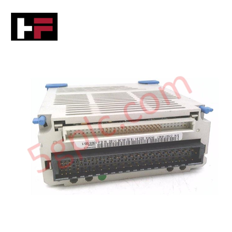
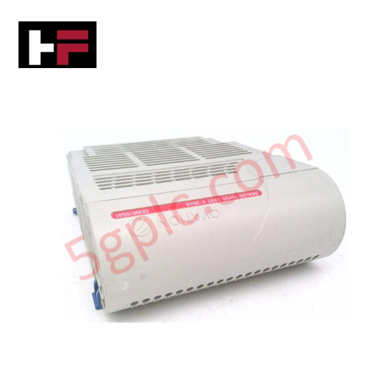
Configured for high-density signal acquisition in Ovation distributed control systems, the Emerson 5X00502G01 (5X00502G01 Analog Input Module) provides direct physical signal processing of analog field inputs. The module facilitates the conversion of field-level current, voltage, and RTD signals into digital format for controller logic execution.
Hardware Specifications
| Parameter | Specification |
|---|---|
| Model | 5X00502G01 |
| Brand | Emerson |
| Origin | USA |
| Weight | 0.45 kg |
| Dimensions | 250 mm x 150 mm x 30 mm |
| Operating Temp | -40 to 70 deg C |
| Power Consumption | 10 W |
| Number of Channels | 8 |
| Input Types | 4-20 mA, 0-10 V, RTD |
| Accuracy | +/- 0.1% of span |
| Resolution | 0.001% of span |
| Input Impedance | 250 kOhm |
| Signal Processing Time | < 10 ms |
Loop Connectivity and Isolation
The 5X00502G01 module incorporates advanced signal conditioning to support 4-20 mA HART loop protocol architectures. Each of the eight input channels provides channel-to-channel isolation to prevent ground loops and electrical interference common in large-scale industrial installations. The architecture supports configurable signal scaling and filtering, allowing the control system to normalize various input ranges effectively while maintaining a high common mode rejection ratio of 60 dB.
Frequently Asked Questions (FAQ)
Q: Does the 5X00502G01 module support hot-swapping during active system operation?
A: Yes, the module is designed for hot-swapping within the Ovation backplane, allowing for replacement without de-energizing the entire I/O rack.
Q: How should the shield wires be terminated for optimal noise suppression?
A: Shield wires must be terminated at the designated chassis ground point provided on the I/O terminal block to minimize EMI/RFI interference on the analog loops.
Field Installation Guidelines
- Verify backplane power is stable before inserting the module into the designated slot.
- Align the module with the card guides and ensure the backplane connector is fully seated.
- Secure the module using the top and bottom captive screws to ensure a proper ground path between the module housing and the rack.
- Terminate field wiring according to the specific loop requirements (current, voltage, or RTD). Ensure all terminal connections are torqued to manufacturer specifications.
- Perform a cold junction compensation (CJC) calibration check if RTD inputs are utilized to ensure temperature measurement accuracy.
Additional Information
- 100% Genuine Parts: All products are original and authentic, ensuring reliable industrial performance.
- 30-Day Refund Guarantee: Return any in-stock item within 30 days in original, unopened packaging for a full refund (excluding shipping and fees).
- 12-Month Warranty: Covers defects in materials or workmanship; excludes misuse, normal wear, or unauthorized modifications.
- Worldwide Shipping: We ship via USPS, UPS, FedEx, and DHL. Delivery times vary by country and may be subject to customs or import fees.
- Support & Contact: Technical and warranty assistance is available anytime. Contact us here: Contact.
- Purchase Guidance: Check product specifications and compatibility carefully before ordering to ensure proper application.


Tech & Buying Guide

Why 24V DC Power Supplies Standardize Modern Industrial Automation
Industrial control cabinets worldwide rely on 24V DC as the universal power standard for field instrumentation, sensors, and controllers. Walk into any manufacturing plant, and you will find PLCs, human-machine interfaces (HMIs), and smart actuators running on extra-low voltage DC. Standardizing on 24V DC enhances operational safety, lowers cabinet footprint, and maintains steady control performance across factory networks.

Essential Motion Control Commands: A Practical Guide for Engineers
Automation engineers often rely on precise position and speed control to drive modern factory machinery. Modern industrial systems, such as Programmable Logic Controllers (PLCs) and Distributed Control Systems (DCS), depend heavily on standardized motion instructions. Mastering these commands ensures operational safety, protects mechanical components, and optimizes cycle times across production lines.

Mastering Modern Industrial Joystick Controls in Heavy Automation
Industrial joysticks play a pivotal role in human-machine interaction across heavy material handling and mobile hydraulics. These tactile controllers translate complex operator movements into precise electrical signals for PLCs, motion controllers, and DCS networks. Consequently, selecting and installing the right joystick architecture ensures operator safety, reduces fatigue, and optimizes equipment performance.