


Product Details
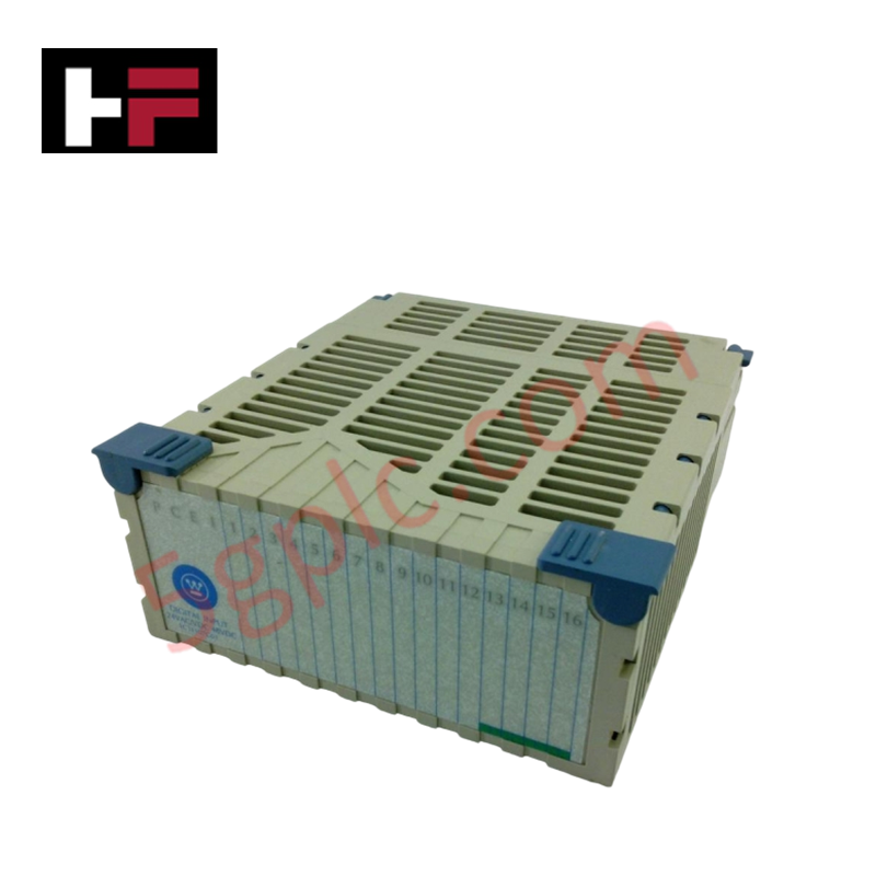
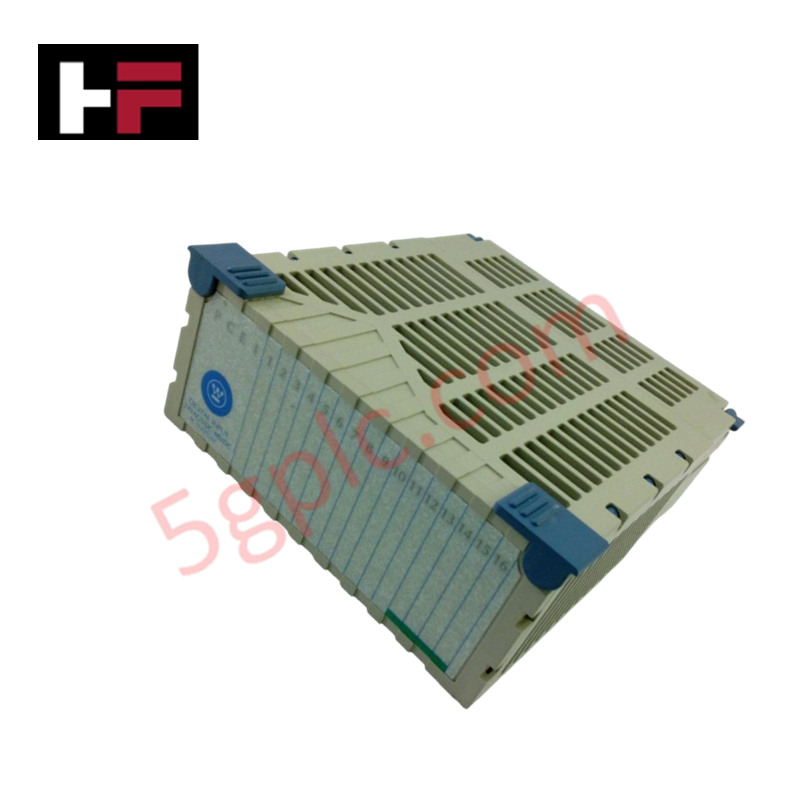
The Emerson 1C31129G04, also cataloged as the 1C31129G04 Analog Output Module, operates as a dedicated hardware component for signal transmission within Ovation control platforms. This module provides direct physical electrical execution to convert digital control values into regulated analog output signals for field-side instrumentation and actuator positioners.
Hardware Specifications
| Parameter | Specification |
|---|---|
| Model | 1C31129G04 |
| Brand | Emerson |
| Origin | United States |
| Weight | 0.3 kg |
| Dimensions | 12.1 cm x 5.4 cm x 14 cm |
| Operating Temp | -40 to 70 deg C |
| Power Consumption | 24 VDC |
| Module Type | Analog Output Module |
Process Control Connectivity
The 1C31129G04 is engineered to maintain signal integrity through integrated channel-to-channel isolation. This electrical barrier prevents common-mode noise and ground loops from affecting output precision when driving multiple field devices. Furthermore, the module supports standard 4-20 mA HART loop protocol architectures, enabling the controller to execute precise setpoints while simultaneously performing diagnostic status monitoring of connected field instruments.
Frequently Asked Questions (FAQ)
Q: Does the 1C31129G04 module support hot-swapping during active system operation?
A: Yes, the module supports hot-swapping within the I/O rack; ensure that no external field voltage is back-fed into the output terminals during the extraction or insertion process to prevent damage to the module circuitry.
Q: Is this module capable of driving high-impedance loads?
A: The output drive capability is defined by the internal voltage compliance of the module; verify that total loop resistance does not exceed the manufacturer-specified limits to ensure accurate current output across the full control range.
Field Installation Guidelines
- Confirm the backplane is de-energized before mounting the module to prevent potential shorts at the connector pins.
- Align the module with the cabinet slot guide and insert until the connector is fully seated against the backplane.
- Terminate field signal wiring at the terminal block using shielded twisted-pair cables to mitigate electromagnetic interference.
- Verify that all shield drain wires are connected to a dedicated chassis ground bus to avoid circulating ground currents.
- Conduct a loop-back verification test using a multimeter to confirm that the analog output values match the commanded digital setpoints before final commissioning.
Additional Information
- 100% Genuine Parts: All products are original and authentic, ensuring reliable industrial performance.
- 30-Day Refund Guarantee: Return any in-stock item within 30 days in original, unopened packaging for a full refund (excluding shipping and fees).
- 12-Month Warranty: Covers defects in materials or workmanship; excludes misuse, normal wear, or unauthorized modifications.
- Worldwide Shipping: We ship via USPS, UPS, FedEx, and DHL. Delivery times vary by country and may be subject to customs or import fees.
- Support & Contact: Technical and warranty assistance is available anytime. Contact us here: Contact.
- Purchase Guidance: Check product specifications and compatibility carefully before ordering to ensure proper application.


Tech & Buying Guide

Why 24V DC Power Supplies Standardize Modern Industrial Automation
Industrial control cabinets worldwide rely on 24V DC as the universal power standard for field instrumentation, sensors, and controllers. Walk into any manufacturing plant, and you will find PLCs, human-machine interfaces (HMIs), and smart actuators running on extra-low voltage DC. Standardizing on 24V DC enhances operational safety, lowers cabinet footprint, and maintains steady control performance across factory networks.

Essential Motion Control Commands: A Practical Guide for Engineers
Automation engineers often rely on precise position and speed control to drive modern factory machinery. Modern industrial systems, such as Programmable Logic Controllers (PLCs) and Distributed Control Systems (DCS), depend heavily on standardized motion instructions. Mastering these commands ensures operational safety, protects mechanical components, and optimizes cycle times across production lines.

Mastering Modern Industrial Joystick Controls in Heavy Automation
Industrial joysticks play a pivotal role in human-machine interaction across heavy material handling and mobile hydraulics. These tactile controllers translate complex operator movements into precise electrical signals for PLCs, motion controllers, and DCS networks. Consequently, selecting and installing the right joystick architecture ensures operator safety, reduces fatigue, and optimizes equipment performance.