










Product Details
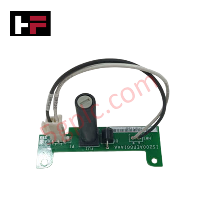
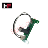
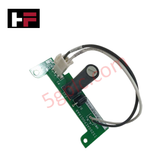
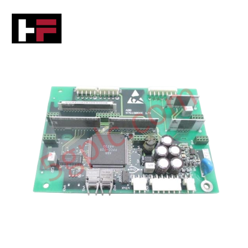
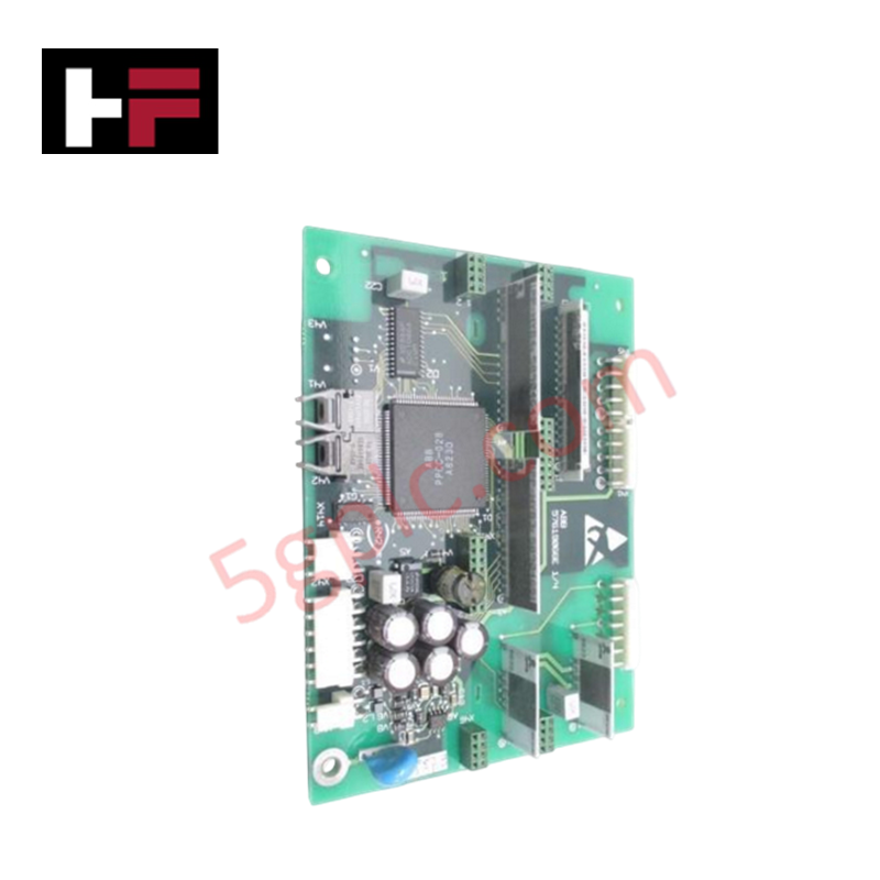
The GE IS200AEPGG1AAA, also cataloged as the IS200AEPG Drive Control Module, operates as a dedicated hardware component for real-time motor control and diagnostic signal processing within GE Drive Control platforms.
Hardware Specifications
| Parameter | Specification |
|---|---|
| Model | IS200AEPGG1AAA |
| Brand | GE |
| Origin | USA |
| Product Type | Drive Control Module |
| Circuit Technology | Surface-mount technology (SMT) |
| Software Interface | ToolboxST application integration |
| Operating Temp | -30 to 65 deg C |
| Dimensions | Standard GE Drive Control card profile |
| Weight | Standard assembly weight |
| Power Consumption | Backplane bus and control power dependent |
I/O Density Scaling & Firmware Flash Compatibility
The drive control module processes high-density I/O signals and drive feedback loops to execute precise speed and torque adjustments. Integrated firmware flash compatibility supports deterministic parameter updates and hardware configuration directly through the ToolboxST application framework. Internal backplane bus communication channels enable real-time monitoring of current, voltage, and thermal diagnostics while maintaining high throughput across control system networks.
Frequently Asked Questions
Q: How are operational parameters and drive logic configured on the module?
A: Hardware configuration and parameter adjustments are executed via the ToolboxST application interface over system communication channels.
Q: What mounting form factor does the circuit assembly utilize?
A: The board features a surface-mount design built on a standard rack card format that plugs directly into designated GE drive control slots.
Q: How does the module handle real-time fault detection and health tracking?
A: Onboard diagnostic circuits continuously sample internal operating conditions, transmitting status flags and event data to the controller for proactive troubleshooting.
Field Installation Guidelines
- Isolate main drive power feed lines and discharge internal DC bus capacitors prior to inserting or removing the module.
- Wear a grounded electrostatic discharge (ESD) wrist strap attached to the metal enclosure frame during handling.
- Slide the circuit card evenly along the rack guides until the rear backplane connectors are fully seated.
- Fasten all front panel retention screws to ensure continuous ground reference and prevent mechanical dislodgement.
- Verify that signal and feedback wiring bundles are routed separately from high-voltage motor output lines.
Additional Information
- 100% Genuine Parts: All products are original and authentic, ensuring reliable industrial performance.
- 30-Day Refund Guarantee: Return any in-stock item within 30 days in original, unopened packaging for a full refund (excluding shipping and fees).
- 12-Month Warranty: Covers defects in materials or workmanship; excludes misuse, normal wear, or unauthorized modifications.
- Worldwide Shipping: We ship via USPS, UPS, FedEx, and DHL. Delivery times vary by country and may be subject to customs or import fees.
- Support & Contact: Technical and warranty assistance is available anytime. Contact us here: Contact.
- Purchase Guidance: Check product specifications and compatibility carefully before ordering to ensure proper application.


Tech & Buying Guide

Understanding Modern SCADA Systems: Architecture, Communication Topologies, and Industrial Applications
Supervisory Control and Data Acquisition (SCADA) systems form the digital backbone of modern industrial automation. They collect critical field data, transmit signals across vast distances, and empower plant operators with real-time process visibility. Across modern infrastructures, SCADA solutions streamline centralized control and maintain continuous operational uptime.
Understanding OPC Servers in Modern Industrial Automation: Principles, Architecture, and Applications
In industrial automation, connecting physical hardware with high-level software remains a primary operational challenge. Factories utilize programmable logic controllers (PLCs), distributed control systems (DCS), human-machine interfaces (HMIs), and smart sensors from diverse vendors. These devices often speak different proprietary protocols. Open Platform Communications (OPC) servers solve this interoperability challenge by standardizing how data flows across factory networks.

Industrial Fiber Optic Cables: Principles, Connectors, and Fusion Splicing Techniques
Modern factory automation relies heavily on fiber optic cables for high-speed industrial data transmission. Fiber optic cables transmit light pulses instead of electrical signals, eliminating electromagnetic interference (EMI) risks completely. Each optical strand consists of a high-purity glass core surrounded by a protective cladding layer. The difference in refractive index between core and cladding enables total internal reflection. Protective resin buffers, Kevlar strength members, and rugged outer jackets safeguard delicate glass cores in harsh environments. Consequently, automation engineers prefer fiber backbones for reliable noise-free communication in industrial control systems.