


Product Details
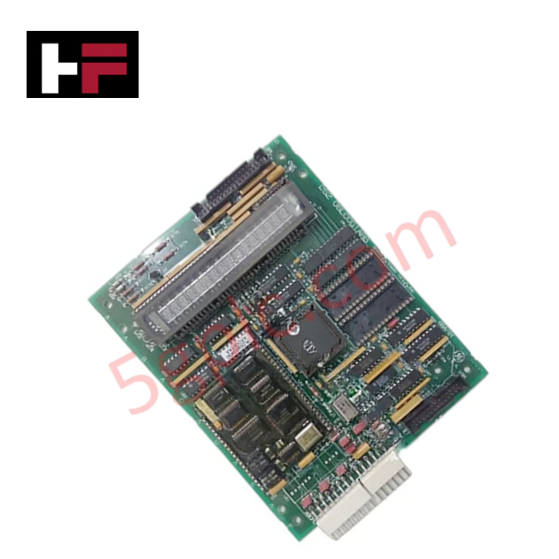
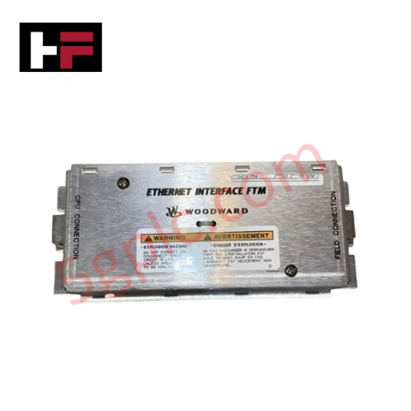
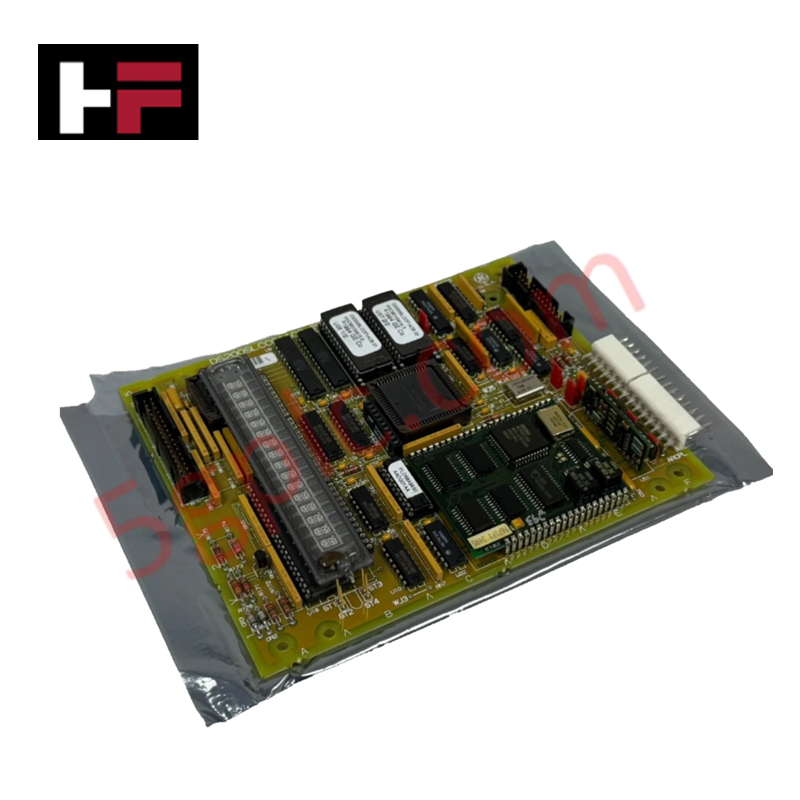
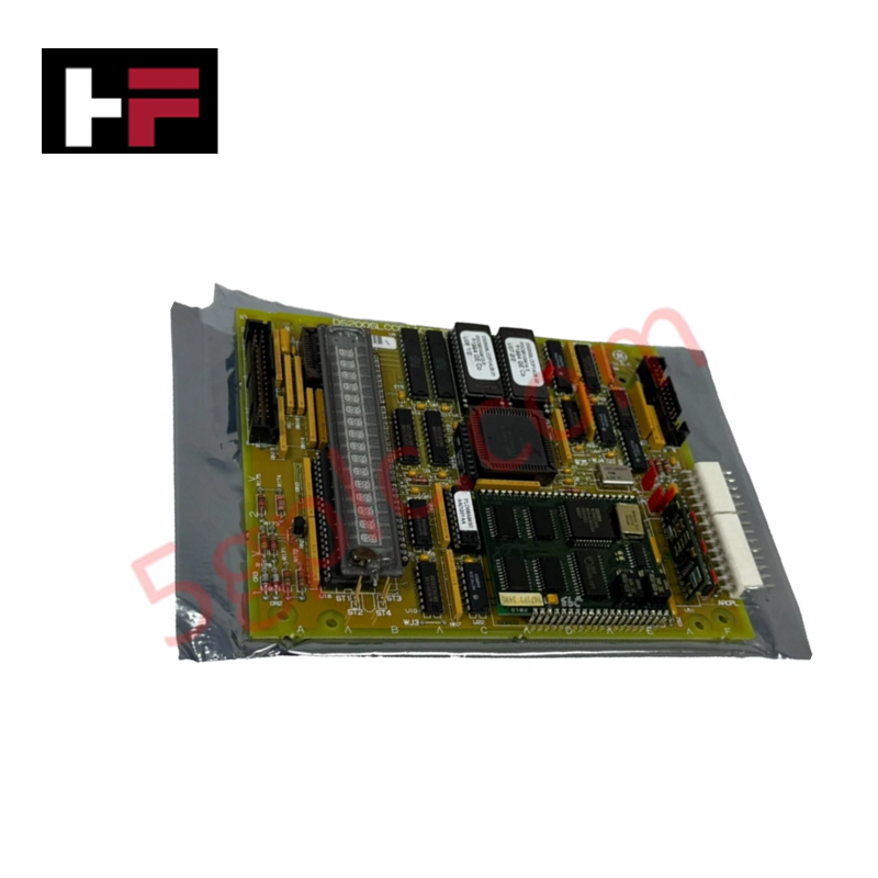
The GE DS200SLCCG1AHH, also cataloged as the DS200SLCCG1A LAN Communication Card, operates as a dedicated hardware component for network interfacing and data exchange within Mark V Speedtronic turbine control systems.
Hardware Specifications
| Parameter | Specification |
|---|---|
| Model | DS200SLCCG1AHH |
| Brand | General Electric |
| Origin | USA |
| Weight | 1500 g |
| Dimensions | 120 mm x 80 mm x 15 mm |
| Operating Temp | 0 deg C to 70 deg C |
| Power Consumption | < 5 W |
| Core Function | LAN communication and processor interfacing |
Industrial Control & Firmware Compatibility
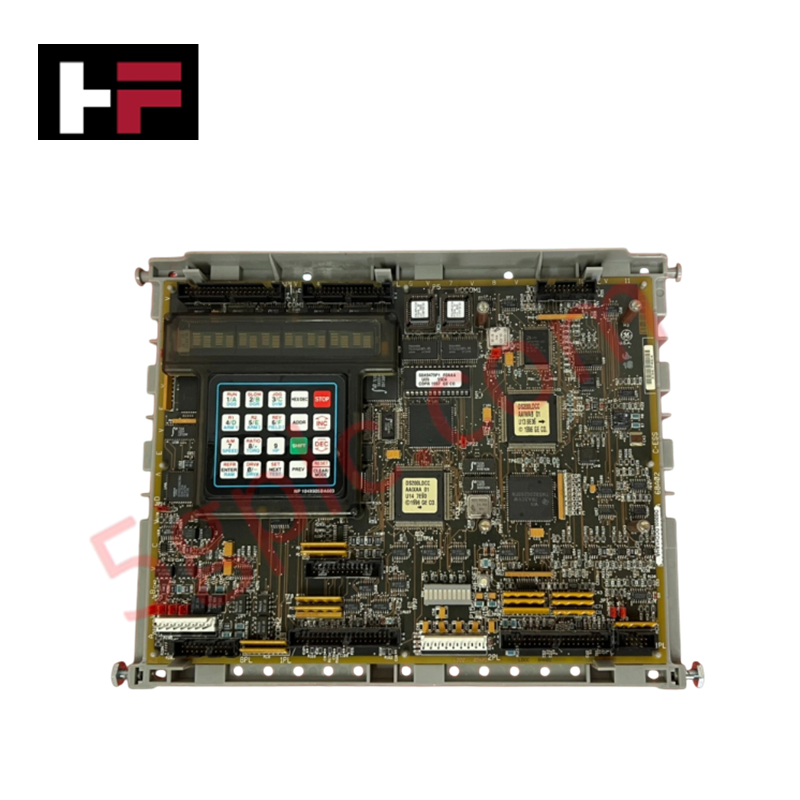
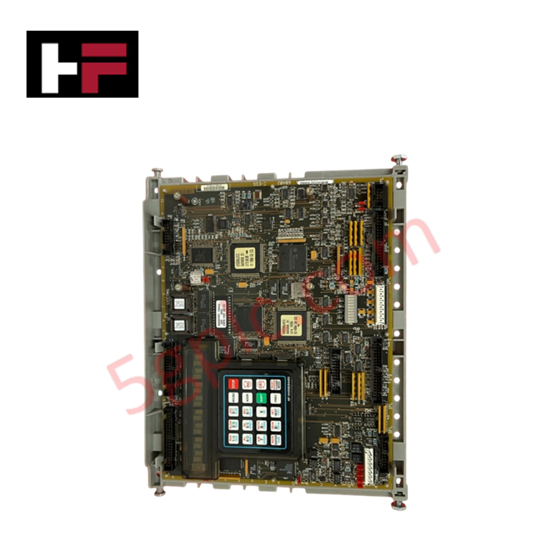
The DS200SLCCG1AHH integrates a LAN Control Processor (LCP) and utilizes dual-ported RAM (U5) for deterministic data exchange with the Drive Control Processor (DCP) on the SDCC card. The module firmware flash compatibility is restricted to the software stored within the two replaceable EPROMs (U6 and U7); these must match the host controller's revision to ensure stable I/O density scaling and timing. The board employs IEEE 802.3x flow control and supports VLAN tagging to maintain network integrity within the Mark V control environment. Configuration requires verification of backplane bus communication velocity to prevent buffer overflows in the onboard U8/U9 RAM arrays during high-traffic network states.
Frequently Asked Questions
Q: Can this module be hot-swapped while the turbine control system is active?
A: Mark V series communication modules are not designed for hot-swapping. Power must be fully isolated from the rack before installation or removal to prevent electrical transients or corruption of the dual-ported RAM data structures.
Q: What is the purpose of the 16-position alphanumeric display on the module?
A: The display, controlled by the U18 controller, provides localized diagnostic feedback when connected to the programmer module via the KPPL interface, allowing for status monitoring of the LCP boot sequence and network communication health.
Field Installation Guidelines
- Physical Mounting: The module features a low-profile form factor. Ensure it is fully seated in the host rack and that the 3PL interface cable is securely connected to the Drive Control Card (SDCC) to prevent communication time-outs.
- Shielding and Grounding: Utilize the RJ-45 interface in compliance with standard Ethernet physical layer requirements. Ensure the cabinet ground strap is intact, as the card utilizes both isolated and non-isolated circuitry; improper grounding can induce noise into the non-isolated signal paths.
- Memory Handling: When replacing EPROMs (U6/U7), utilize appropriate ESD mitigation tools. Ensure the EPROM orientation aligns with the PCB silk-screen markings to prevent damage to the U1 LCP during the initialization sequence.
- Component Inspection: Periodically verify the integrity of the RJ-45 connector and the 16-position display ribbon cable. Environmental contaminants in the cabinet can lead to oxidation of these contact points, resulting in intermittent network connectivity.
Additional Information
- 100% Genuine Parts: All products are original and authentic, ensuring reliable industrial performance.
- 30-Day Refund Guarantee: Return any in-stock item within 30 days in original, unopened packaging for a full refund (excluding shipping and fees).
- 12-Month Warranty: Covers defects in materials or workmanship; excludes misuse, normal wear, or unauthorized modifications.
- Worldwide Shipping: We ship via USPS, UPS, FedEx, and DHL. Delivery times vary by country and may be subject to customs or import fees.
- Support & Contact: Technical and warranty assistance is available anytime. Contact us here: Contact.
- Purchase Guidance: Check product specifications and compatibility carefully before ordering to ensure proper application.


Tech & Buying Guide

Selecting the Right Cables for Industrial Automation: A Comprehensive Guide
Selecting the appropriate cabling infrastructure is critical for the success of any industrial automation project. Improper cable selection often leads to signal degradation, system instability, and costly downtime. As an automation engineer, I frequently see projects compromised by poor cabling choices in harsh industrial environments. This guide simplifies the complex landscape of cabling to help you make informed decisions for your PLC, DCS, and control systems.

Preventing Spurious Trips in Emergency Stop Systems: A Technical Guide
In industrial automation, the Emergency Stop (E-Stop) pushbutton is the ultimate safety line. However, relying on a single Normally-Closed (NC) contact can sometimes lead to unexpected spurious trips. As a control systems engineer, I have seen these nuisance trips halt entire production lines, causing significant downtime. Understanding why these components fail and how to implement robust architecture is essential for any reliable DCS or PLC-based safety system.

Sequencing Induction Motor Control with PLC Logic: Best Practices
In modern industrial automation, controlling a group of induction motors requires precision and safety. Uncontrolled simultaneous startup of multiple large motors often causes significant voltage dips, potentially triggering protective trips. Therefore, implementing a sequential startup and shutdown strategy is essential. This approach minimizes inrush current and ensures the system operates within established power constraints. A robust PLC program serves as the ideal engine for orchestrating these sequences.