


Product Details
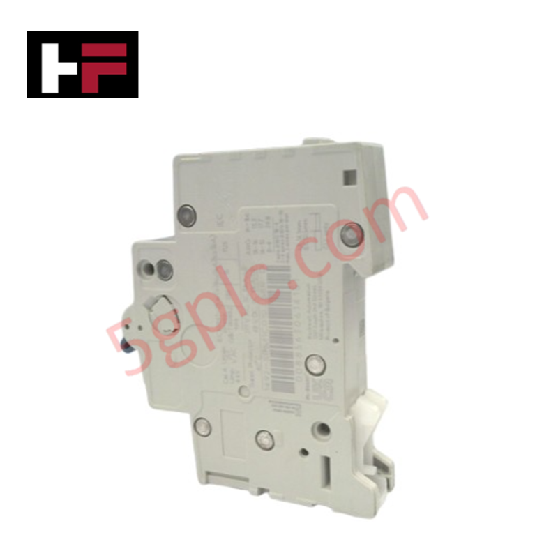
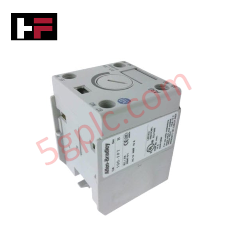
Configured for overcurrent protection in control circuit branches, the Allen-Bradley 1492-SPM1C040 (1492-SPM1C040 Supplementary Protector) provides direct physical/electrical execution of single-pole circuit interruption under overload and short-circuit conditions.
Hardware Specifications
| Parameter | Specification |
|---|---|
| Model | 1492-SPM1C040 |
| Brand | Allen-Bradley |
| Origin | USA |
| Weight | 0.11 kg |
| Dimensions | Not Specified |
| Operating Temp | Not Specified |
| Power Consumption | Not Applicable |
| Current Rating | 4 A |
| Number of Poles | 1 Pole |
| Trip Curve | C-Curve |
Profinet / EtherNet/IP Deterministic Networks
The 1492-SPM1C040 utilizes a thermal-magnetic trip unit to provide instantaneous response to fault events. This protector is designed for mounting within standard control enclosures where I/O density scaling necessitates individual branch circuit isolation. While this device serves as a mechanical circuit protection component, its operation is governed by standard electrical coordination protocols. Users must ensure the protector is matched to the load requirements and that the upstream fault current does not exceed the device's rated breaking capacity. Firmware flash compatibility and deterministic network diagnostics are handled by secondary monitoring devices where status feedback is required for supervisory logic.
Frequently Asked Questions
Q: Can this 1-pole protector be used for motor branch circuit protection?
A: No. The 1492-SPM1C040 is classified as a supplementary protector and is intended for protection of control circuits and instrumentation. It does not meet the requirements for a UL-listed branch circuit protector intended for direct motor branch circuit protection.
Q: Does the C-curve trip characteristic allow for inrush current?
A: Yes. The C-curve is specifically designed for general-purpose applications with moderate inrush currents. It allows for higher transient currents during the initial energization phase without causing nuisance tripping, while maintaining tight protection against sustained overloads and short circuits.
Field Installation Guidelines
- Mount the protector onto a standard 35 mm DIN rail; ensure the mounting latch is fully seated to provide mechanical stability.
- Observe the designated line and load terminal orientations; incoming power should be connected to the upper terminals.
- Utilize copper conductors sized according to the 4 A continuous current rating to prevent excessive heat generation at the termination points.
- Separate the protected control circuit wiring from high-voltage power lines or variable frequency drive cables to mitigate electromagnetic noise.
- Apply the correct tightening torque to the clamp terminals as specified in the technical manual to ensure a low-impedance electrical path.
- Perform a continuity test upon completion of wiring to verify that the circuit is correctly established and that the breaker is functional in the "ON" position.
Additional Information
- 100% Genuine Parts: All products are original and authentic, ensuring reliable industrial performance.
- 30-Day Refund Guarantee: Return any in-stock item within 30 days in original, unopened packaging for a full refund (excluding shipping and fees).
- 12-Month Warranty: Covers defects in materials or workmanship; excludes misuse, normal wear, or unauthorized modifications.
- Worldwide Shipping: We ship via USPS, UPS, FedEx, and DHL. Delivery times vary by country and may be subject to customs or import fees.
- Support & Contact: Technical and warranty assistance is available anytime. Contact us here: Contact.
- Purchase Guidance: Check product specifications and compatibility carefully before ordering to ensure proper application.


Tech & Buying Guide
PLC vs. PAC: Navigating Selection in Modern Industrial Automation
Selecting the right controller is a fundamental decision in industrial automation. While the lines between Programmable Logic Controllers (PLC) and Programmable Automation Controllers (PAC) often blur, understanding their core architectural differences is essential for system reliability. Both controllers serve as the brain of control systems, yet their specific capabilities dictate their suitability for various factory automation tasks.
Transforming Textile Manufacturing: The Strategic Integration of Industrial Automation and AI
The textile industry stands at a critical technological crossroads. Legacy operations must now embrace digital transformation to remain competitive in a global market. By integrating advanced industrial automation—ranging from PLC-controlled machinery to sophisticated AI-driven analytics—manufacturers can significantly boost productivity, minimize material waste, and elevate overall product quality.
Navigating Industrial Communication Protocols: A Technical Guide for Modern PLCs
In the realm of industrial automation, the Programmable Logic Controller (PLC) serves as the brain of the factory floor. However, its true power is unlocked through robust communication protocols. These digital pathways ensure seamless data exchange between controllers, sensors, and enterprise-level management systems.