


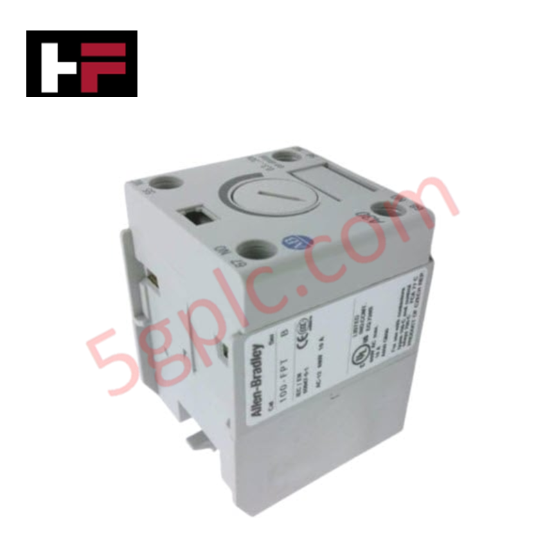
Product Details
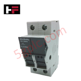
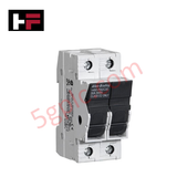
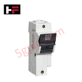
The ALLEN BRADLEY 1492-FB2M30, also cataloged as the 1492-FB2M30 Panel Accessory, operates as a dedicated hardware component for overcurrent protection and circuit isolation within industrial control panels. This unit facilitates the physical housing and electrical termination of midget-style fuses to protect downstream control circuits.
Hardware Specifications
| Parameter | Specification |
|---|---|
| Model | 1492-FB2M30 |
| Brand | ALLEN BRADLEY |
| Origin | USA |
| Weight | 0.20 lbs |
| Dimensions | Standard DIN-rail mount footprint |
| Operating Temp | -20 deg C to 60 deg C (typical for 1492 series) |
| Power Consumption | Passive Component |
| Pole Configuration | 2 Pole |
| Current Rating | 30 A |
| Fuse Type | 1 1/2 inch x 13/32 inch (Midget) |
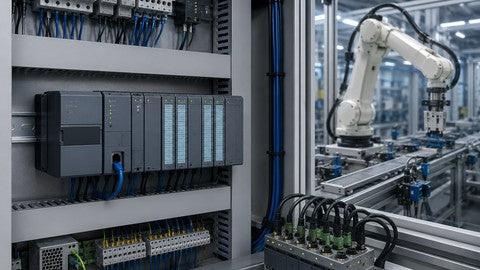
Industrial Control System Integration and Mounting Stability
The 1492-FB2M30 is designed for high-density mounting within industrial enclosures. Achieving optimal DIN-rail mounting stability is required to ensure consistent electrical contact between the fuse holder busbar and the rail. Proper torque application to the terminal screws is necessary to maintain the integrity of the connection, preventing localized heating due to resistive losses. The modular design allows for ganging multiple units, though thermal dissipation profiles must be calculated based on the cumulative power loss of the individual fuses under full load current to prevent exceeding the ambient enclosure temperature limits.
Frequently Asked Questions
Q: Does the 1492-FB2M30 support hot-swapping under load?
A: No, this device is not rated for load-break operations. The circuit must be de-energized before removing or inserting fuses to prevent electrical arcing and operator injury.
Q: Is this fuse holder compatible with different DIN-rail standards?
A: The device is designed for standard 35 mm DIN-rail mounting. Ensure the rail is properly grounded to the enclosure backplane to maintain circuit shielding and surge protection continuity.
Field Installation Guidelines
- Mounting: Snap the unit onto a 35 mm DIN-rail. Ensure the locking tab is fully engaged. If ganging multiple holders, ensure the alignment is flush to distribute mechanical stress evenly across the rail.
- Wiring: Strip wires to the recommended length (refer to the terminal lug specifications). Use copper conductors sized for 30 A capacity (minimum 10 AWG). Tighten terminal screws to the manufacturer's specified torque to avoid loose connections and thermal degradation.
- Grounding: While the holder is a passive component, the metal rail must be bonded to the enclosure's protective earth (PE) busbar to ensure compliance with electrical safety standards and to provide a low-impedance path for potential fault currents.
Additional Information
- 100% Genuine Parts: All products are original and authentic, ensuring reliable industrial performance.
- 30-Day Refund Guarantee: Return any in-stock item within 30 days in original, unopened packaging for a full refund (excluding shipping and fees).
- 12-Month Warranty: Covers defects in materials or workmanship; excludes misuse, normal wear, or unauthorized modifications.
- Worldwide Shipping: We ship via USPS, UPS, FedEx, and DHL. Delivery times vary by country and may be subject to customs or import fees.
- Support & Contact: Technical and warranty assistance is available anytime. Contact us here: Contact.
- Purchase Guidance: Check product specifications and compatibility carefully before ordering to ensure proper application.


Tech & Buying Guide
PLC vs. PAC: Navigating Selection in Modern Industrial Automation
Selecting the right controller is a fundamental decision in industrial automation. While the lines between Programmable Logic Controllers (PLC) and Programmable Automation Controllers (PAC) often blur, understanding their core architectural differences is essential for system reliability. Both controllers serve as the brain of control systems, yet their specific capabilities dictate their suitability for various factory automation tasks.
Transforming Textile Manufacturing: The Strategic Integration of Industrial Automation and AI
The textile industry stands at a critical technological crossroads. Legacy operations must now embrace digital transformation to remain competitive in a global market. By integrating advanced industrial automation—ranging from PLC-controlled machinery to sophisticated AI-driven analytics—manufacturers can significantly boost productivity, minimize material waste, and elevate overall product quality.
Navigating Industrial Communication Protocols: A Technical Guide for Modern PLCs
In the realm of industrial automation, the Programmable Logic Controller (PLC) serves as the brain of the factory floor. However, its true power is unlocked through robust communication protocols. These digital pathways ensure seamless data exchange between controllers, sensors, and enterprise-level management systems.