


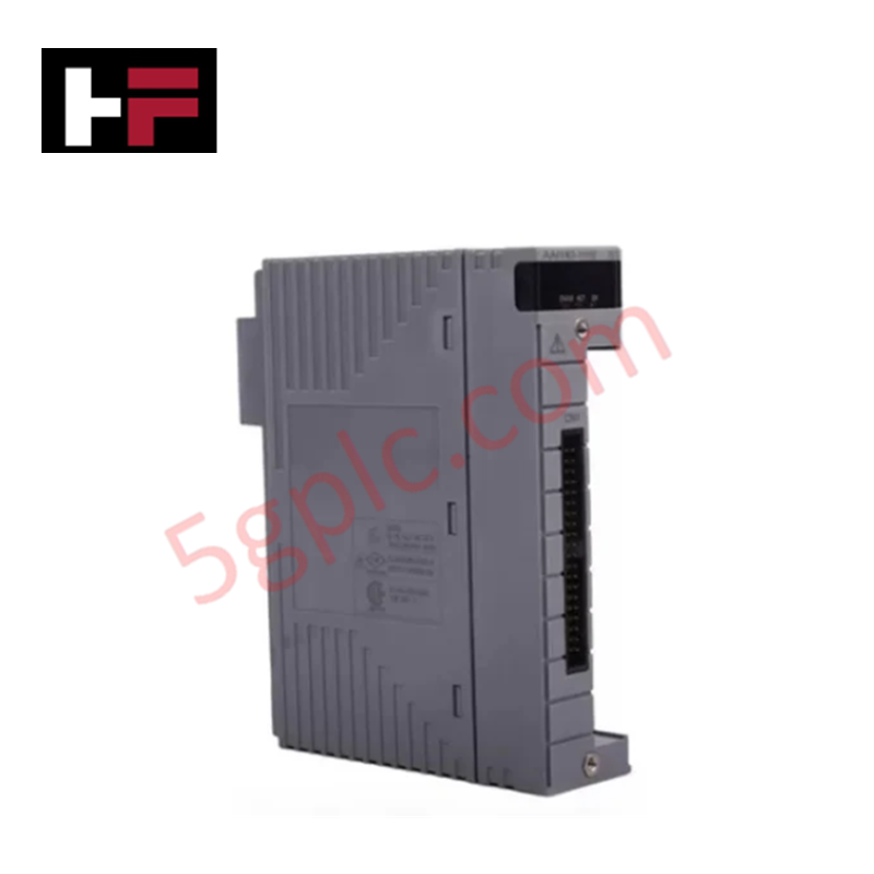
Product Details
Product Overview
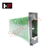
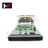
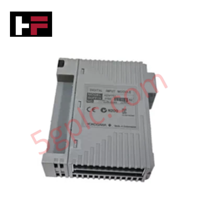
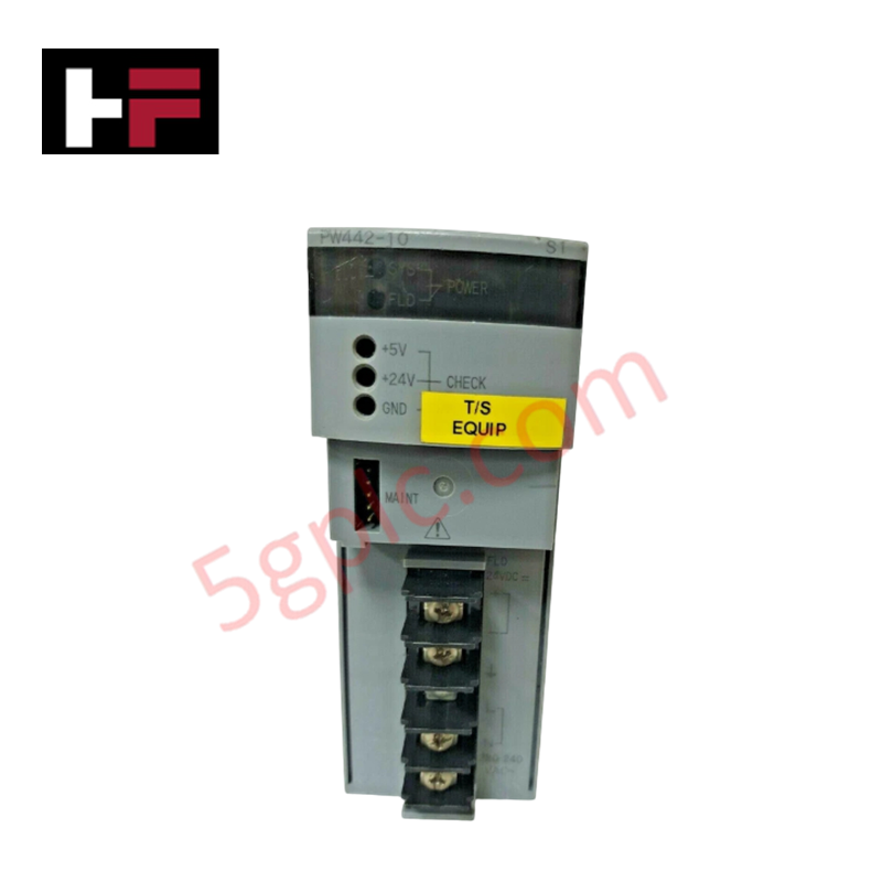
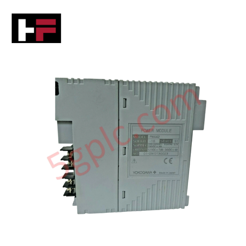
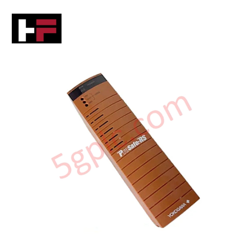
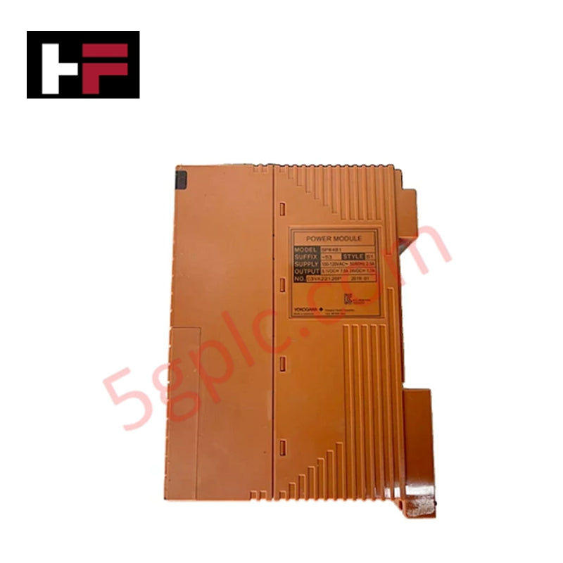
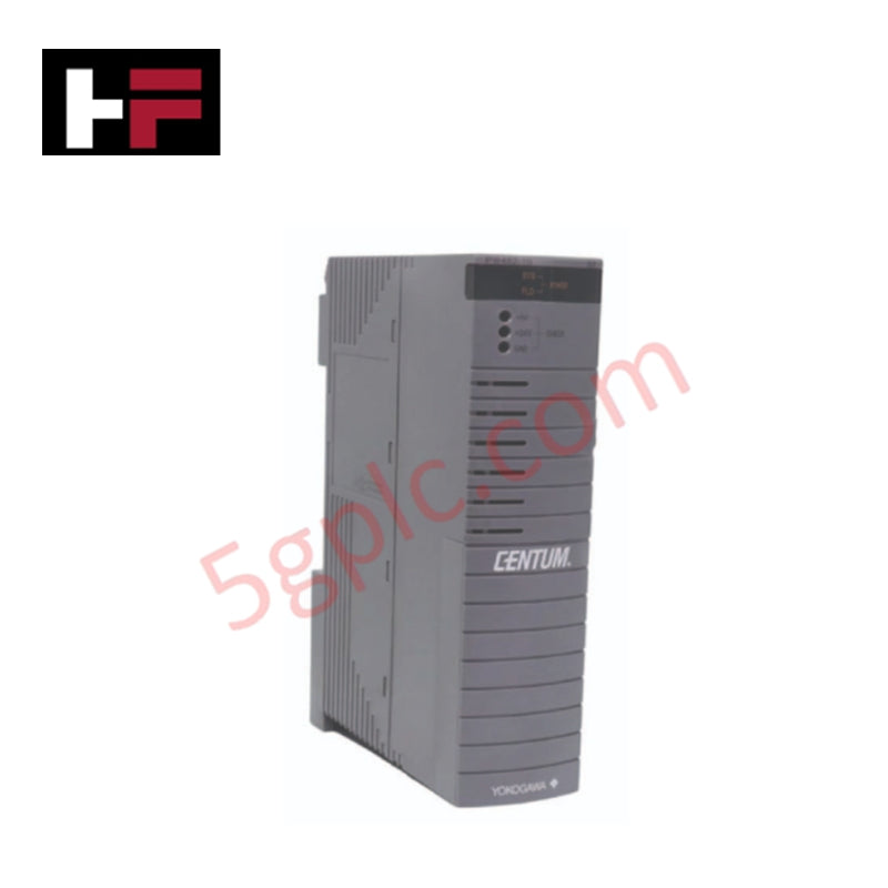
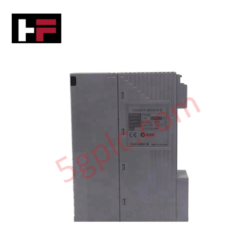
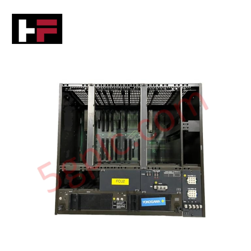
The Yokogawa AIP552-S1 Bus Converter Module serves as a critical interoperability gateway within the CENTUM VP and CS 3000 Distributed Control Systems (DCS), engineered to bridge the proprietary high-speed V-Net control network with third-party fieldbus protocols such as Modbus and PROFIBUS. In modern industrial plants where legacy equipment and diverse vendor devices must coexist, this module solves the challenge of data silos by enabling seamless, real-time bidirectional communication between Yokogawa control stations and external subsystems. By handling protocol conversion locally with deterministic latency, the AIP552-S1 ensures that vital process data from non-Yokogawa devices is accurately integrated into the DCS for unified monitoring, alarming, and control, thereby maximizing plant visibility without requiring costly system-wide replacements.
Technical Specifications
|
Parameter |
Specification |
|---|---|
|
Model Number |
AIP552 |
|
Style Code |
S1 |
|
Manufacturer |
Yokogawa Electric Corporation |
|
Product Type |
Bus Converter / Gateway Module |
|
System Compatibility |
CENTUM VP, CENTUM CS 3000 |
|
Primary Interface |
V-Net (Yokogawa Proprietary Control Bus) |
|
Supported Secondary Protocols |
Modbus (RTU/TCP), PROFIBUS-DP, and other configurable fieldbuses |
|
Power Supply |
24 VDC (Nominal) |
|
Operating Voltage Range |
19.2 – 30 VDC (Industrial Tolerance) |
|
Operating Temperature |
0°C to 55°C (32°F to 131°F) |
|
Storage Temperature |
-20°C to 70°C |
|
Physical Dimensions |
6.0" × 2.0" × 10.0" (15.2 cm × 5.1 cm × 25.4 cm) |
|
Unit Weight |
1 lb 3.0 oz (0.5 kg) |
|
Mounting Style |
Backplane Slot Mount (CENTUM VP Node) |
|
Data Integrity |
CRC checking, parity verification, and timeout monitoring |
|
Diagnostic Features |
LED status indicators for V-Net link and Fieldbus activity |
Model Code Decomposition
Yokogawa's communication and gateway modules utilize a strict naming convention where the base part number defines the protocol function, and the "Style" suffix indicates the specific hardware revision, supported protocol stack version, and firmware compatibility.
Part Number: AIP552-S1
-
AIP: Series prefix for CENTUM VP/CS 3000 peripheral and interface hardware.
-
5: Functional category denoting "Network Interface" or "Communication Processor" modules.
-
52: Unique designator for the Multi-Protocol Bus Converter.
-
The "5" in the tens place typically correlates to advanced communication gateways.
-
The "2" sequence specifically identifies the unit capable of converting V-Net to open standards like Modbus and PROFIBUS.
-
-S1 (Style 1): This suffix is mandatory and indicates the specific hardware revision and loaded protocol firmware.
-
S1: Represents the primary production revision of the AIP552. It defines the specific memory map, baud rate support, and master/slave configuration logic compatible with CENTUM VP R3.x and later systems.
-
Compatibility Logic: The "S1" style ensures that the internal mapping tables align with the Vx-Toolset engineering software. Using a different style (e.g., S2) without corresponding firmware updates in the host station may result in communication failures or incorrect data scaling. The suffix guarantees the module possesses the correct physical layer drivers for the specified fieldbus protocols.
Installation Recommendations and Wiring Guidelines
Proper installation of the AIP552-S1 is essential to ensure reliable protocol conversion and prevent noise-induced communication errors on both the V-Net and fieldbus segments.
-
Protocol Configuration: Before physical installation, use the CENTUM VP engineering tool (Vx-Toolset) to define the communication parameters. Configure the specific protocol (e.g., Modbus RTU vs. TCP, PROFIBUS baud rate) and map the register addresses to DCS tags. The module does not auto-negotiate complex fieldbus parameters.
-
Power Verification: Ensure the backplane or external supply provides a stable 24 VDC. Voltage drops below 19 VDC can cause the module to reset or drop communication packets. Use a dedicated power line if possible to avoid noise from heavy loads.
-
Fieldbus Wiring:
-
Modbus: Use shielded twisted pair cables. For RS-485 connections, ensure proper termination resistors (120 Ω) are installed at both ends of the daisy chain.
-
PROFIBUS: Utilize standard purple PROFIBUS cable with active terminators enabled at the ends of the segment. Verify the station address matches the configuration in the DCS.
-
Grounding and Isolation: Ground the cable shields at a single point (typically the control room ground) to prevent ground loops. The AIP552-S1 provides electrical isolation between the V-Net backplane and the fieldbus ports; maintain this isolation by avoiding common grounding paths between the two networks.
-
Backplane Insertion: Insert the module firmly into the designated communication slot until the rear connector engages fully. Secure the front locking lever immediately to prevent vibration loosening.
-
Diagnostic Verification: Upon power-up, observe the front panel LEDs. A steady green light typically indicates valid V-Net communication, while blinking activity lights on the fieldbus port confirm data exchange. Use the DCS diagnostic view to check for "Communication Error" or "Timeout" alarms during the initial commissioning phase.
Frequently Asked Questions (FAQ)
Q: Can the AIP552-S1 handle multiple protocols simultaneously?
A: The AIP552-S1 is typically configured for one primary secondary protocol per instance (e.g., either Modbus or PROFIBUS) depending on the specific firmware load associated with the "S1" style. To support multiple different protocols in one station, multiple AIP552 modules or a higher-density gateway unit may be required. Consult the specific hardware manual for your firmware version.
Q: Is the AIP552-S1 hot-swappable?
A: Yes, the module supports hot-swapping within the CENTUM VP architecture. However, removing the module will temporarily interrupt communication with all field devices connected to that specific gateway. It is recommended to perform replacement during a maintenance window or ensure redundant paths are available if critical control loops depend on this data.
Q: What is the maximum distance for the Modbus connection?
A: For Modbus RTU (RS-485), the maximum distance is typically 1,200 meters (4,000 feet) at lower baud rates (e.g., 9600 bps). At higher speeds, the distance decreases. Repeaters should be used for longer runs. For Modbus TCP, standard Ethernet cabling limits (100m per segment) apply.
Q: How do I troubleshoot communication failures?
A: First, check the LED status indicators on the module. Then, use the CENTUM VP system view to monitor error counters (CRC errors, timeouts). Verify that the baud rate, parity, and stop bits match exactly between the AIP552 configuration and the external field devices. Finally, check physical wiring for loose terminals or broken shields.
Q: Does this module come pre-configured?
A: No. The AIP552-S1 is shipped with factory default firmware. All protocol parameters, device addresses, and data mapping must be configured by the system integrator using the Yokogawa Vx-Toolset engineering software to match the specific plant requirements.
Additional Information
- 100% Genuine Parts: All products are original and authentic, ensuring reliable industrial performance.
- 30-Day Refund Guarantee: Return any in-stock item within 30 days in original, unopened packaging for a full refund (excluding shipping and fees).
- 12-Month Warranty: Covers defects in materials or workmanship; excludes misuse, normal wear, or unauthorized modifications.
- Worldwide Shipping: We ship via USPS, UPS, FedEx, and DHL. Delivery times vary by country and may be subject to customs or import fees.
- Support & Contact: Technical and warranty assistance is available anytime. Contact us here: Contact.
- Purchase Guidance: Check product specifications and compatibility carefully before ordering to ensure proper application.
Tech & Buying Guide

Mastering Modern Industrial Joystick Controls in Heavy Automation
Industrial joysticks play a pivotal role in human-machine interaction across heavy material handling and mobile hydraulics. These tactile controllers translate complex operator movements into precise electrical signals for PLCs, motion controllers, and DCS networks. Consequently, selecting and installing the right joystick architecture ensures operator safety, reduces fatigue, and optimizes equipment performance.

Navigating Industrial Automation Failures: Types, Causes, and Mitigation Strategies
Modern manufacturing relies heavily on automated control systems to maximize throughput and maintain product quality. However, unplanned downtime in industrial automation can cost facility operators thousands of dollars per hour. Understanding how programmable logic controllers (PLCs), distributed control systems (DCS), and field instrumentation fail empowers engineering teams to implement robust preventive maintenance strategies.

Essential Motion Control Commands: A Practical Guide for Engineers
Automation engineers often rely on precise position and speed control to drive modern factory machinery. Modern industrial systems, such as Programmable Logic Controllers (PLCs) and Distributed Control Systems (DCS), depend heavily on standardized motion instructions. Mastering these commands ensures operational safety, protects mechanical components, and optimizes cycle times across production lines.