


Product Details
Product Overview
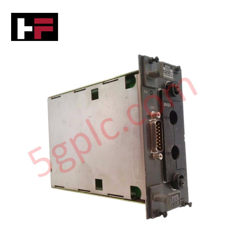
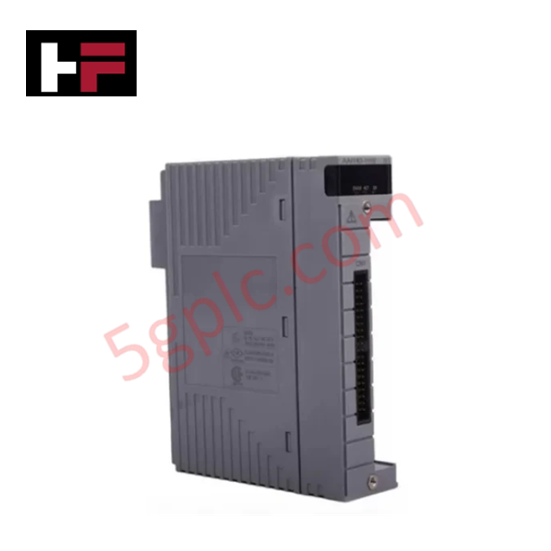
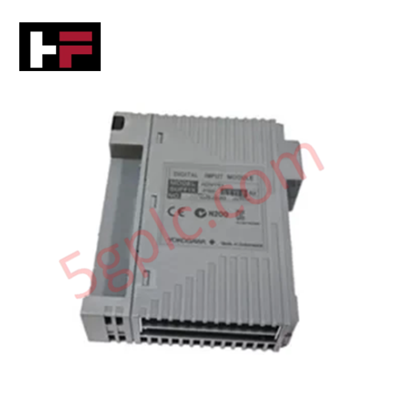
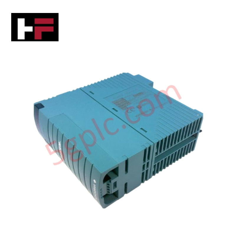
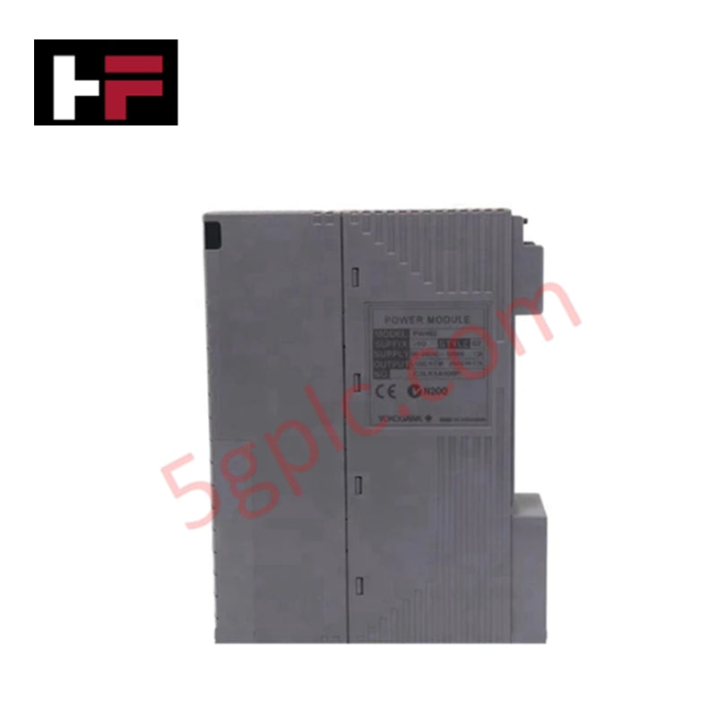
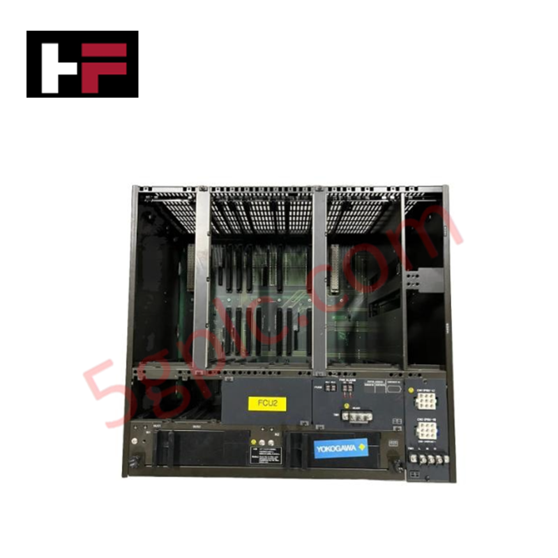
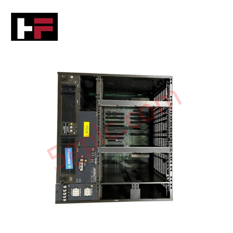
The Yokogawa AIP503-S1 V-Net Coupler Module serves as the critical communication backbone for CENTUM CS and CENTUM VP Distributed Control Systems (DCS), providing deterministic, high-integrity data transmission between field control stations, human interface stations, and engineering workstations. In mission-critical process environments where network latency or packet loss can compromise safety and production continuity, this module solves the challenge of reliable real-time communication by implementing Yokogawa's proprietary V-Net protocol over robust 10BASE-5 physical media. Designed for 24 VDC operation in harsh industrial conditions, the AIP503-S1 ensures seamless integration of control loops, alarm management, and historical data logging across power generation, oil refining, and chemical processing facilities.
Technical Specifications
|
Parameter |
Specification |
|---|---|
|
Model Number |
AIP503 |
|
Style Code |
S1 |
|
Manufacturer |
Yokogawa Electric Corporation |
|
Product Type |
V-Net Coupler Module (Network Interface) |
|
System Compatibility |
CENTUM CS 3000, CENTUM VP (FCS/HIS/ENG Stations) |
|
Network Protocol |
V-Net (Yokogawa Proprietary Real-Time Control Bus) |
|
Physical Layer |
10BASE-5 (Thick Ethernet Coaxial) |
|
Data Transfer Rate |
10 Mbps (Deterministic Token-Passing Architecture) |
|
Power Supply |
24 VDC (Nominal, derived from host station backplane) |
|
Operating Voltage Range |
19.2–30 VDC (Industrial tolerance) |
|
Physical Dimensions |
7.6 cm (W) × 15.2 cm (H) × 17.8 cm (D) |
|
Unit Weight |
1.75 lbs (0.79 kg) |
|
Operating Temperature |
0°C to 50°C (32°F to 122°F) |
|
Storage Temperature |
-20°C to 70°C |
|
Operating Humidity |
10% to 90% RH (Non-condensing) |
|
Mounting Style |
Backplane Slot Mount (CENTUM VP Node) |
|
Network Topology |
Bus (Multi-drop with termination) |
|
Max Segment Length |
500 meters per 10BASE-5 segment (with repeaters) |
|
Diagnostic Features |
Link status monitoring, CRC error counting, collision detection |
Model Code Decomposition
Yokogawa's communication modules employ a precise suffix convention to denote hardware revision, protocol implementation, and firmware compatibility. The "Style" identifier is mandatory for ensuring the coupler integrates correctly with the CENTUM VP/CS network stack.
Part Number: AIP503-S1
-
AIP: Series prefix for CENTUM VP/CS 3000 peripheral and interface hardware, covering communication, I/O, and storage units.
-
5: Functional category denoting "Network Interface" or "Communication Processor" modules within Yokogawa's architecture.
-
03: Unique designator for the V-Net Coupler implementing the 10BASE-5 physical layer.
-
The "0" in the tens place typically correlates to real-time control network interfaces.
-
The "3" sequence specifically identifies the V-Net protocol stack with thick coaxial (10BASE-5) transceiver integration.
-
-S1 (Style 1): Critical suffix indicating the hardware revision and firmware mapping.
-
S1: Denotes the primary production revision of the AIP503, featuring a specific V-Net controller firmware version, transceiver calibration, and timing parameters compatible with CENTUM VP R3.03+ and CENTUM CS 3000 V10.x+ systems.
-
Compatibility Warning: Substituting an S1 module with a different style (e.g., S2, S3) or a generic Ethernet interface will result in network initialization failure, as the V-Net protocol requires precise token-passing timing and proprietary frame formatting. The "S1" suffix ensures exact electrical characteristics and firmware handshake compatibility with the host station's operating system.
-
Physical Layer Note: The AIP503-S1 implements 10BASE-5 (thick coaxial) which requires N-series connectors and proper 50-Ω termination at segment ends. It is not compatible with 10BASE-T (RJ45) or modern fiber V-Net variants without media converters.
Installation Recommendations and Wiring Guidelines
Proper installation of the AIP503-S1 is essential to maintain V-Net network integrity and prevent communication faults in critical control loops.
-
Network Planning: Before installation, verify the V-Net segment topology. The AIP503-S1 supports bus topology with a maximum of 100 nodes per segment and 500 meters total cable length. Ensure proper placement of terminators (50 Ω, 1/2 W) at both physical ends of the coaxial run.
-
Coaxial Cable Preparation: Use RG-8/U or equivalent 50-Ω thick coaxial cable with double shielding. Strip the outer jacket carefully to avoid damaging the braid shield. Install N-series connectors with proper crimping tools to ensure 50-Ω impedance continuity and prevent signal reflection.
-
Grounding and Shielding: Ground the coaxial cable shield at one end only (typically the control room ground bus) to prevent ground loops while maintaining EMI rejection. Ensure the module chassis is bonded to the cabinet ground per Yokogawa system grounding specifications.
-
Backplane Insertion: With the station powered down (or in maintenance mode), align the AIP503-S1 with the designated communication slot. Slide firmly until the rear connector engages fully with the backplane. Secure the front retention lever immediately to prevent vibration-induced disconnection.
-
Termination Verification: After physical installation but before energizing, use an ohmmeter to verify 25 Ω resistance across the segment (two 50-Ω terminators in parallel). Incorrect termination is the leading cause of V-Net communication errors.
-
Network Initialization: Upon power-up, use the CENTUM VP system maintenance tools to initialize the V-Net configuration. Verify node addresses, token rotation time, and diagnostic counters. Monitor for CRC errors or collisions during the first 24 hours of operation.
-
Environmental Protection: Route coaxial cables away from high-voltage AC lines, motor leads, and VFD outputs. Maintain minimum 30 cm separation to prevent electromagnetic interference from corrupting the 10 Mbps signal.
Frequently Asked Questions (FAQ)
Q: Can the AIP503-S1 be used with modern Ethernet-based V-Net/IP networks?
A: No. The AIP503-S1 implements the legacy 10BASE-5 physical layer for traditional V-Net. For V-Net/IP (Ethernet-based) networks, Yokogawa offers different coupler modules (e.g., AIP55x series). The two protocols are not interoperable without gateway devices.
Q: Is the AIP503-S1 hot-swappable in a running CENTUM VP system?
A: Physically, the module slides into a slot that supports hot-swapping. However, replacing a primary V-Net coupler in an active control station will temporarily interrupt communication to that node. It is recommended to perform replacement during a planned maintenance window or ensure redundant network paths are active before removal.
Q: What is the maximum distance between AIP503-S1 modules on a V-Net segment?
A: The total segment length for 10BASE-5 V-Net is limited to 500 meters. Individual tap distances between nodes should not exceed 2.5 meters from the main coaxial trunk. For longer distances, Yokogawa-approved repeaters or fiber optic converters must be used.
Q: How do I diagnose communication issues with the AIP503-S1?
A: Use the CENTUM VP diagnostic tools to monitor V-Net status: check link LED indicators on the module front panel, review CRC error counters in the system view, and verify token rotation time. Common issues include improper termination, damaged coaxial connectors, or ground loops.
Q: Do you supply this module as new or refurbished?
A: We supply 100% brand-new, original factory-sealed Yokogawa AIP503-S1 modules. We do not sell refurbished or pulled units for critical control applications to ensure maximum reliability and warranty coverage.
Q: What is the lead time for shipping?
A: We maintain stock of the AIP503-S1 for immediate dispatch. Orders are typically processed and shipped via DHL/FedEx within 24 to 72 hours, with global delivery usually achieved within 3-5 business days.
Additional Information
- 100% Genuine Parts: All products are original and authentic, ensuring reliable industrial performance.
- 30-Day Refund Guarantee: Return any in-stock item within 30 days in original, unopened packaging for a full refund (excluding shipping and fees).
- 12-Month Warranty: Covers defects in materials or workmanship; excludes misuse, normal wear, or unauthorized modifications.
- Worldwide Shipping: We ship via USPS, UPS, FedEx, and DHL. Delivery times vary by country and may be subject to customs or import fees.
- Support & Contact: Technical and warranty assistance is available anytime. Contact us here: Contact.
- Purchase Guidance: Check product specifications and compatibility carefully before ordering to ensure proper application.
Tech & Buying Guide

Mastering Modern Industrial Joystick Controls in Heavy Automation
Industrial joysticks play a pivotal role in human-machine interaction across heavy material handling and mobile hydraulics. These tactile controllers translate complex operator movements into precise electrical signals for PLCs, motion controllers, and DCS networks. Consequently, selecting and installing the right joystick architecture ensures operator safety, reduces fatigue, and optimizes equipment performance.

Navigating Industrial Automation Failures: Types, Causes, and Mitigation Strategies
Modern manufacturing relies heavily on automated control systems to maximize throughput and maintain product quality. However, unplanned downtime in industrial automation can cost facility operators thousands of dollars per hour. Understanding how programmable logic controllers (PLCs), distributed control systems (DCS), and field instrumentation fail empowers engineering teams to implement robust preventive maintenance strategies.

Essential Motion Control Commands: A Practical Guide for Engineers
Automation engineers often rely on precise position and speed control to drive modern factory machinery. Modern industrial systems, such as Programmable Logic Controllers (PLCs) and Distributed Control Systems (DCS), depend heavily on standardized motion instructions. Mastering these commands ensures operational safety, protects mechanical components, and optimizes cycle times across production lines.