










Product Details
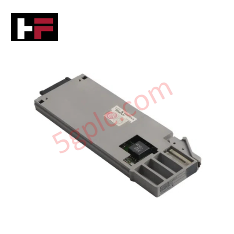
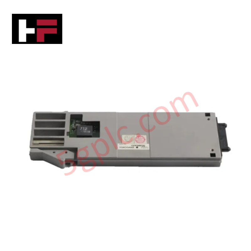
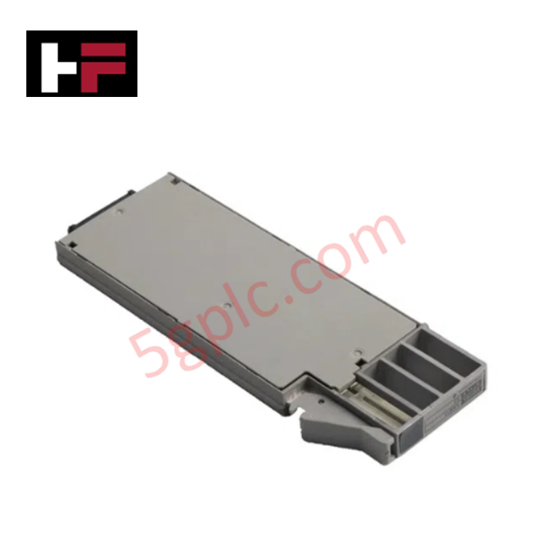
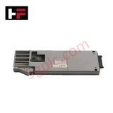
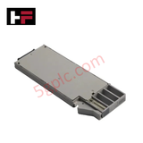
The Yokogawa AAM50 S1, also cataloged as the AAM50 Analog Output Module, operates as a dedicated hardware component for 4-20 mA DC current loop signal generation within Yokogawa CENTUM CS 3000 DCS platforms.
Hardware Specifications
| Parameter | Specification |
|---|---|
| Model | AAM50 S1 |
| Brand | Yokogawa |
| Origin | Japan |
| Weight | 0.4 kg |
| Dimensions | 130 x 30 x 100 mm |
| Operating Temp | -20 deg C to 60 deg C |
| Power Consumption | 5 W |
| Power Supply | 24 VDC |
| Output Channels | 8 isolated current output channels |
| Output Signal Range | 4-20 mA DC |
| Isolation Type | Channel-to-channel galvanic isolation |
| System Compatibility | Yokogawa CENTUM CS 3000 |
Channel-to-Channel Isolation and 4-20 mA Current Loop Execution
The AAM50 S1 analog output module incorporates independent channel-to-channel galvanic isolation across all 8 current output paths to suppress ground potential differentials and common-mode electrical noise. Each output channel converts digital control commands from the CENTUM CS 3000 backplane into isolated 4-20 mA DC analog signals. This isolated execution structure prevents ground loops between field actuators, control valve positioners, and panel indicators, preserving signal integrity across all field control loops.
Frequently Asked Questions
Q: What is the primary function of individual channel isolation on the AAM50 S1 module?
A: Individual channel isolation breaks ground loops between field devices and the DCS rack, preventing common-mode noise and stray potential differences from interfering with adjacent 4-20 mA current outputs.
Q: Can the AAM50 S1 module output channels drive inductive loads directly?
A: The 4-20 mA DC channels are engineered for analog signal driving into valve positioners, I/P converters, and drive inputs. Inductive switching devices must be driven via external interposing relay barriers rather than direct analog outputs.
Q: What occurs on an output channel during an external short-circuit condition?
A: Internal current-limiting circuitry restricts short-circuit current to safe operating limits on the affected channel, protecting internal digital-to-analog conversion circuits while adjacent channels maintain normal operation.
Field Installation Guidelines
- Rack Mounting: Slide the module vertically into the designated CENTUM I/O slot along the chassis guide rails. Hand-tighten top and bottom retaining screws to establish structural retention and backplane ground contact.
- Signal Cabling: Route 4-20 mA current loops using twisted shielded pair cables (AWG 18 to AWG 22). Maintain a minimum physical distance of 300 mm from high-voltage AC conductors to prevent inductive coupling.
- Shield Termination: Connect cable shields to the main functional earth (FE) ground bar inside the control cabinet at one end only. Do not connect shield drain wires to field instrument housings.
- Supply Check: Verify that the incoming 24 VDC power supply remains within nominal voltage tolerances under full 8-channel, 20 mA loop load conditions.
Additional Information
- 100% Genuine Parts: All products are original and authentic, ensuring reliable industrial performance.
- 30-Day Refund Guarantee: Return any in-stock item within 30 days in original, unopened packaging for a full refund (excluding shipping and fees).
- 12-Month Warranty: Covers defects in materials or workmanship; excludes misuse, normal wear, or unauthorized modifications.
- Worldwide Shipping: We ship via USPS, UPS, FedEx, and DHL. Delivery times vary by country and may be subject to customs or import fees.
- Support & Contact: Technical and warranty assistance is available anytime. Contact us here: Contact.
- Purchase Guidance: Check product specifications and compatibility carefully before ordering to ensure proper application.





Tech & Buying Guide

Human-Machine Interface Design: Essential Guide to HMI Selection, Visualization, and Control System Integration
Human-Machine Interfaces (HMIs) serve as the primary operational window into complex industrial automation systems. Modern HMIs convert raw machine data into clear graphical displays, enabling operators to oversee entire manufacturing processes in real time. Instead of relying on physical control panels full of hardwired switches, engineers program interactive screens using intuitive graphics, dynamic color coding, and responsive touch interfaces. Over my 15 years in control systems engineering, I have observed HMIs transform from basic display screens into sophisticated command centers that drive operational efficiency across DCS and PLC environments.

Understanding Safety Relays in Industrial Automation: Architecture, Operation, and Functional Safety
Standard electromechanical relays provide basic electrical isolation between low-voltage control circuits and high-power output loads. A traditional switching relay features a magnetic coil driving mechanical Common (COM), Normally-Open (NO), and Normally-Closed (NC) contacts. However, standard relays pose severe functional risks when deployed in critical safety interlock circuits. High current inrush or mechanical wear can weld contacts together permanently. If contact welding occurs in an emergency stop circuit, pressing the button fails to halt hazardous machinery movements. Consequently, global functional safety standards prohibit standard relays for critical machine guarding functions.

Mastering Wire Identification in Industrial Automation: The Power of Ferrules and Cross-Ferruling
Proper wire labeling forms the cornerstone of reliable control system installation and long-term maintenance. In complex industrial automation environments, technicians terminate thousands of conductor ends inside control panels, marshalling racks, and field junction boxes. Ferrules serve as individual tube-shaped sleeve markers slipped onto conductors before final termination. While technicians historically relied on pre-printed individual letter rings, modern control panel builders utilize automated ferrule printing machines. These thermal-transfer printers generate durable, single-sleeve heat-shrink tags directly matching approved wiring schematics, significantly accelerating cabinet assembly workflows.