


Product Details
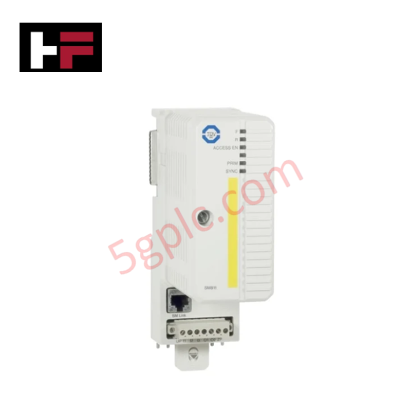
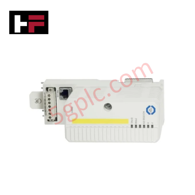
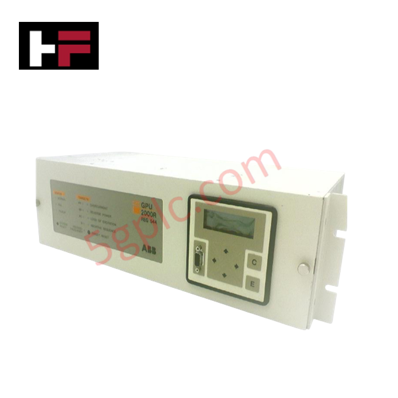
Configured for overspeed detection in turbine control systems, the Woodward 8237-1369 (8237-1369 Overspeed Protection System) provides direct electrical execution of triple modular redundant (TMR) speed sensing and safety trip logic.
Hardware Specifications
| Parameter | Specification |
|---|---|
| Model | 8237-1369 |
| Brand | Woodward |
| Dimensions | 330 mm x 445 mm x 159 mm |
| Operating Temp | -20 deg C to +60 deg C |
| Power Consumption | 90 W (HV) / 100 W (LV) |
| Speed Signal Input | 100-32,000 Hz (MPU) / 0.5-25,000 Hz (Proximity) |
| Trip Output | 8 A at 220 VAC / 8 A at 24 VDC |
Actuator Loop Feedback Response and Thermal Heat Sink Dissipation Profiles
The 8237-1369 utilizes a TMR architecture requiring three independent speed inputs to monitor prime mover rotational frequency. The system performs continuous monitoring for overspeed or signal loss conditions, utilizing a 2-out-of-3 voting logic for shutdown relay execution. To manage high-speed transient response, the internal logic is optimized to process MPU (1-35 Vrms) or proximity probe signals while maintaining thermal heat sink dissipation profiles conducive to cabinet-mounted electronics. The analog 4-20 mA output stages are isolated to ensure speed meter accuracy, and the de-energize-to-trip architecture ensures that the system defaults to a safe state upon internal failure. The input stages must be properly shielded to prevent electromagnetic interference from inducing false counts within the 1-320 gear tooth range.
Frequently Asked Questions
Q: How does the system resolve signal discrepancies between the three speed sensing modules?
A: The 8237-1369 uses a voting logic gate to compare the three speed signals. If one sensor input diverges or indicates a failure, the system flags the fault while the remaining two modules continue to provide protection logic, preventing unnecessary turbine trips.
Q: Can the shutdown relay outputs be used for direct actuator control?
A: The shutdown relays are rated for 8 A at 220 VAC or 24 VDC and are intended for safety-critical circuit interruption. Direct high-current inductive load switching should be evaluated for arc suppression requirements to preserve relay contact longevity.
Field Installation Guidelines
- Mounting: Mount the unit either via bulkhead (wall/skid) or flush-mount vertically within a cabinet. Ensure the 330 mm x 445 mm x 159 mm envelope has sufficient airflow to comply with the -20 to +60 deg C operating range.
- Ingress Protection: The unit is rated for IP56. Ensure all conduit entries utilize appropriate cable glands and seals to maintain environmental integrity.
- Wiring: Terminate speed signals (MPU or Proximity) using shielded twisted-pair cabling. Ground the shield at the cabinet end only to prevent ground loops.
- Redundancy: Connect both high-voltage (88-264 VAC / 90-150 VDC) and low-voltage (18-32 VDC) power inputs if redundant power sourcing is required to ensure continuous protection during primary source failure.
Additional Information
- 100% Genuine Parts: All products are original and authentic, ensuring reliable industrial performance.
- 30-Day Refund Guarantee: Return any in-stock item within 30 days in original, unopened packaging for a full refund (excluding shipping and fees).
- 12-Month Warranty: Covers defects in materials or workmanship; excludes misuse, normal wear, or unauthorized modifications.
- Worldwide Shipping: We ship via USPS, UPS, FedEx, and DHL. Delivery times vary by country and may be subject to customs or import fees.
- Support & Contact: Technical and warranty assistance is available anytime. Contact us here: Contact.
- Purchase Guidance: Check product specifications and compatibility carefully before ordering to ensure proper application.

Tech & Buying Guide

Mastering Functional Safety Terminology in Industrial Automation
In modern process control and factory automation, managing operational risk is a top engineering priority. High-speed machinery, high-pressure vessels, and continuous processes present constant hazards to personnel and equipment. Modern plant operations rely heavily on functional safety strategies to mitigate these risks. This guide breaks down the essential functional safety terminology that every control systems engineer should master.

Understanding Dry Contacts in PLC Wiring: An Industrial Automation Guide
Mastering contact switching principles is essential for reliable control panels. Field devices and PLCs interface through dry or wet contacts. This technical guide examines the mechanics of dry contacts, explores their wiring architectures, and evaluates their key advantages in industrial automation.

Ultimate Commissioning Checklist for Industrial Automation Systems: An Engineering Guide
Commissioning is the most decisive phase of an industrial automation project, transforming control hardware and software into an operational facility. Thorough testing prevents costly startup delays and builds customer confidence. This guide covers essential checklists, electrical standards, and best practices.