


Product Details
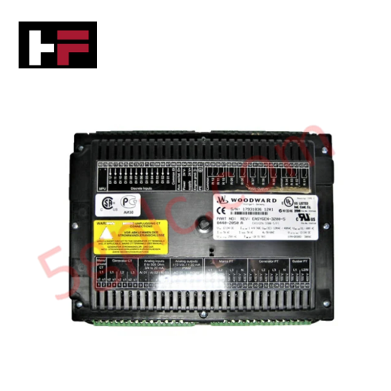
Configured for overspeed detection in turbine control systems, the Woodward 8200-205 (8200-205 Overspeed Protection System) provides direct electrical execution of triple modular redundant (TMR) speed sensing and trip logic.
Hardware Specifications
| Parameter | Specification |
|---|---|
| Model | 8200-205 |
| Brand | Woodward |
| Weight | 13.06 lbs |
| Dimensions | 19.0 in x 12.24 in x 5.62 in |
| Operating Temp | -15 deg C to +60 deg C |
| Power Consumption | Not specified |
| Input Voltage | 220 VAC |
| Trip Frequency | 250 Hz to 25 kHz |
Actuator Loop Feedback Response and Load Management
The 8200-205 utilizes a TMR architecture requiring three independent magnetic pickup inputs to monitor prime mover rotational frequency. The system performs continuous monitoring for overspeed conditions and loss-of-signal scenarios, utilizing de-energize-to-trip logic for fail-safe operation. The controller supports internal self-diagnostics to detect CPU and MPU failures, reporting status via the integrated display and keypad interface. To maintain signal integrity within the sensing loops, cable runs should be minimized, and shielding must be applied to prevent electromagnetic interference from inducing false speed readings. The operational environment must comply with IP54 and NEMA 4/4X standards to ensure the longevity of internal electronics against moisture and dust ingress.
Frequently Asked Questions
Q: Can the operational modes (PROGRAM vs. MONITOR) be accessed without the physical key?
A: No. Mode switching is strictly hardware-locked to prevent unauthorized configuration changes. Key lock access is mandatory for any adjustment to the internal protection parameters or turbine start/reset methods.
Q: How does the system handle a loss-of-signal condition in one of the three magnetic pickup channels?
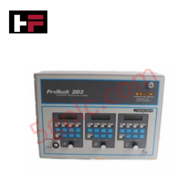
A: The ProTech 203 system continually compares inputs across the three channels. A loss-of-signal in a single channel triggers an indication, allowing the system to maintain protection logic while identifying the faulty input sensor for maintenance intervention.
Field Installation Guidelines
- Mounting: Ensure the enclosure is mounted on a rigid, vibration-isolated surface. Adhere to NEMA 4/4X standards for enclosure integrity, utilizing appropriate cable glands for all conduit entries.
- Wiring: Connect the three magnetic pickups to the dedicated sensing inputs. Use high-quality shielded twisted-pair cabling for all speed signals, ensuring the shield is terminated to the common ground bus within the protection cabinet.
- Configuration: Upon installation, verify the selected turbine start method (separate start/reset or combined start/reset) according to the site-specific control requirements defined in manual 85205.
- Testing: Perform a low-speed simulation test prior to turbine startup to verify that the trip-point frequency ranges (250 Hz to 25 kHz) are correctly calibrated to the specific prime mover's speed characteristics.
Additional Information
- 100% Genuine Parts: All products are original and authentic, ensuring reliable industrial performance.
- 30-Day Refund Guarantee: Return any in-stock item within 30 days in original, unopened packaging for a full refund (excluding shipping and fees).
- 12-Month Warranty: Covers defects in materials or workmanship; excludes misuse, normal wear, or unauthorized modifications.
- Worldwide Shipping: We ship via USPS, UPS, FedEx, and DHL. Delivery times vary by country and may be subject to customs or import fees.
- Support & Contact: Technical and warranty assistance is available anytime. Contact us here: Contact.
- Purchase Guidance: Check product specifications and compatibility carefully before ordering to ensure proper application.

Tech & Buying Guide

Mastering Functional Safety Terminology in Industrial Automation
In modern process control and factory automation, managing operational risk is a top engineering priority. High-speed machinery, high-pressure vessels, and continuous processes present constant hazards to personnel and equipment. Modern plant operations rely heavily on functional safety strategies to mitigate these risks. This guide breaks down the essential functional safety terminology that every control systems engineer should master.

Understanding Dry Contacts in PLC Wiring: An Industrial Automation Guide
Mastering contact switching principles is essential for reliable control panels. Field devices and PLCs interface through dry or wet contacts. This technical guide examines the mechanics of dry contacts, explores their wiring architectures, and evaluates their key advantages in industrial automation.

Ultimate Commissioning Checklist for Industrial Automation Systems: An Engineering Guide
Commissioning is the most decisive phase of an industrial automation project, transforming control hardware and software into an operational facility. Thorough testing prevents costly startup delays and builds customer confidence. This guide covers essential checklists, electrical standards, and best practices.