


Product Details
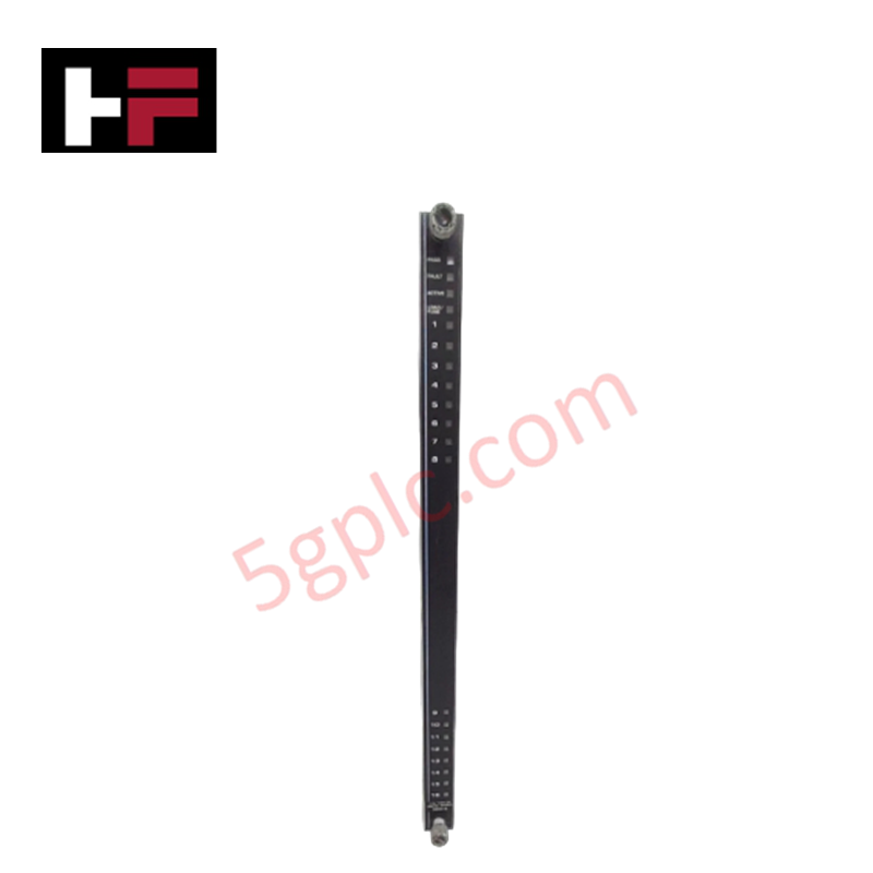
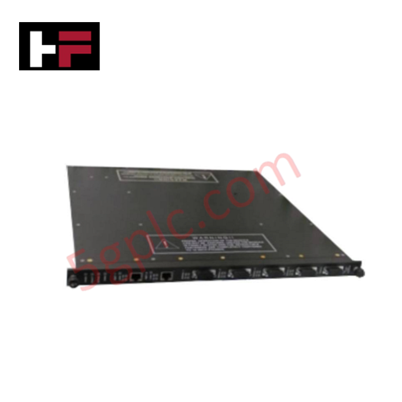
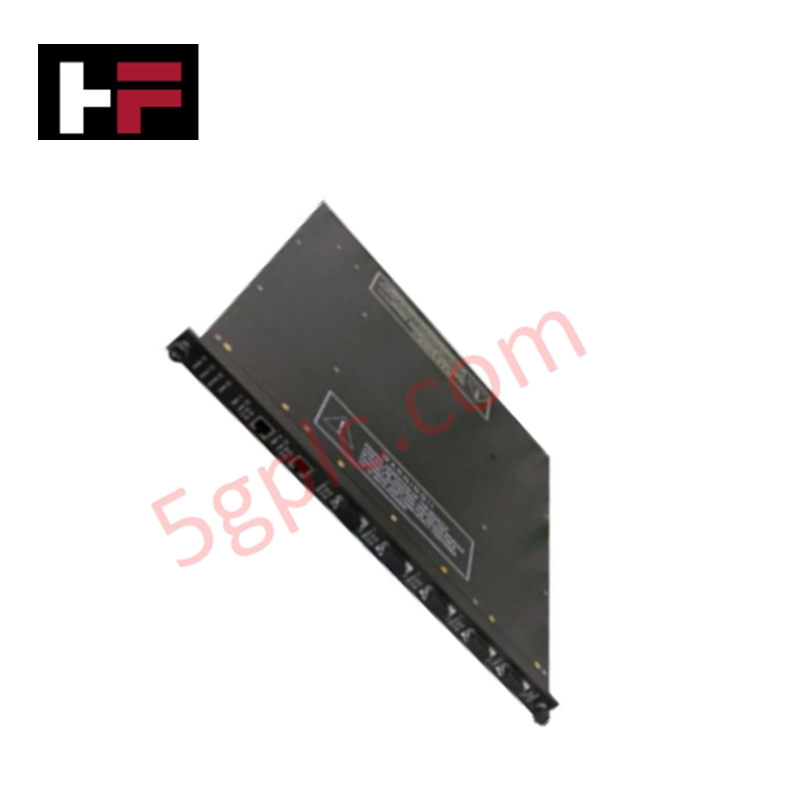
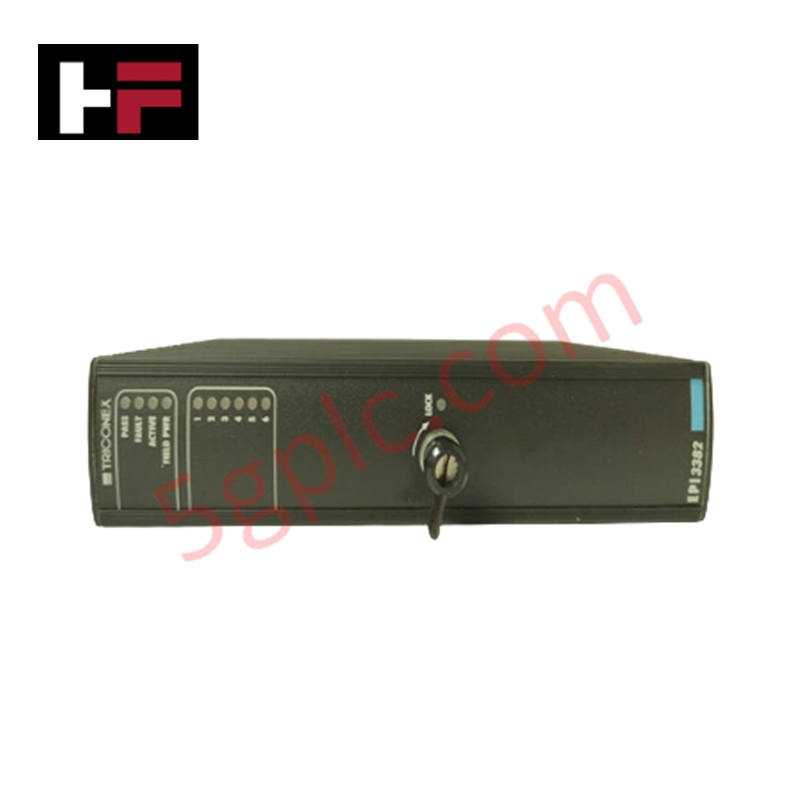
The Triconex PI3381, also cataloged as the 3381 Pulse Input Module, operates as a dedicated hardware component for high-speed pulse signal acquisition and process interface monitoring within Tricon safety system platforms.
Hardware Specifications
| Parameter | Specification |
|---|---|
| Model | PI3381 |
| Brand | Triconex |
| Dimensions | Standard Tricon module form factor |
| Operating Temp | Industrial standard range |
| Input Type | Differential |
| Max Operating Voltage | +/- 33 VDC |
| Sensor Compatibility | Magnetic, active, open-collector |
TMR Safety System and Signal Integrity
The Triconex PI3381 is architected for deployment within a triple modular redundancy (TMR) 2oo3 safety environment. The module performs high-resolution signal processing, utilizing majority-voting logic to determine the validity of incoming pulse data across redundant channels. Galvanic isolation is employed to decouple the field-side sensor loops from the system backplane, preventing the propagation of noise and transient voltages. As a component of a SIL3 certified system, the PI3381 supports fail-safe state execution; should diagnostic monitoring detect an invalid input state or component deviation, the module transitions to a defined safe state to maintain process integrity and ensure deterministic system behavior.
Frequently Asked Questions
Q: Does the PI3381 module support hot-swapping under load?
A: Yes, the module supports hot-swapping within an energized chassis. Upon insertion, the system performs an automated diagnostic handshake to integrate the new module into the TMR voting matrix before active channel processing resumes.
Q: What are the primary input sensitivity requirements for differential signals?
A: The module requires a minimum differential input of 500 mV P-P for the frequency range of 2 Hz to 32,000 Hz. Signal levels below these thresholds may result in intermittent data capture or diagnostic fault triggers.
Field Installation Guidelines
- Confirm the target chassis slot is configured for a pulse/process interface module.
- Align the module with the chassis guide rails and apply firm, steady pressure until the backplane connector is fully seated.
- Tighten the front-panel captive screws to ensure a proper ground connection to the cabinet frame.
- Utilize shielded cabling for all differential input signals, terminating the cable shield at the designated cabinet ground bus to minimize electromagnetic interference.
- Perform a verification check of the input frequency scaling via the system software after installation to ensure alignment with connected sensor pulse outputs.
Additional Information
- 100% Genuine Parts: All products are original and authentic, ensuring reliable industrial performance.
- 30-Day Refund Guarantee: Return any in-stock item within 30 days in original, unopened packaging for a full refund (excluding shipping and fees).
- 12-Month Warranty: Covers defects in materials or workmanship; excludes misuse, normal wear, or unauthorized modifications.
- Worldwide Shipping: We ship via USPS, UPS, FedEx, and DHL. Delivery times vary by country and may be subject to customs or import fees.
- Support & Contact: Technical and warranty assistance is available anytime. Contact us here: Contact.
- Purchase Guidance: Check product specifications and compatibility carefully before ordering to ensure proper application.


Tech & Buying Guide

Strategic Selection: Choosing the Right SCADA Software for Your PLC Project
In industrial automation, the SCADA (Supervisory Control and Data Acquisition) system acts as the bridge between raw machine data and actionable human intelligence. Selecting the incorrect software platform can lead to integration bottlenecks, scalability issues, and excessive long-term maintenance costs. As an automation consultant with 15 years of experience, I have guided many projects through the selection process. Below are the essential criteria for choosing a platform that ensures both performance and longevity.

Ensuring Operational Continuity: The Strategic Value of Redundant Automation Systems
In modern industrial landscapes, unplanned downtime is the ultimate adversary. For sectors relying on complex PLC and DCS architectures, a single hardware failure can trigger catastrophic production losses. Therefore, implementing redundant automation systems is no longer a luxury; it is a fundamental requirement for mission-critical operations. In this article, I analyze why redundancy remains the backbone of reliable industrial infrastructure.

Selecting the Right Cables for Industrial Automation: A Comprehensive Guide
Selecting the appropriate cabling infrastructure is critical for the success of any industrial automation project. Improper cable selection often leads to signal degradation, system instability, and costly downtime. As an automation engineer, I frequently see projects compromised by poor cabling choices in harsh industrial environments. This guide simplifies the complex landscape of cabling to help you make informed decisions for your PLC, DCS, and control systems.