


Product Details
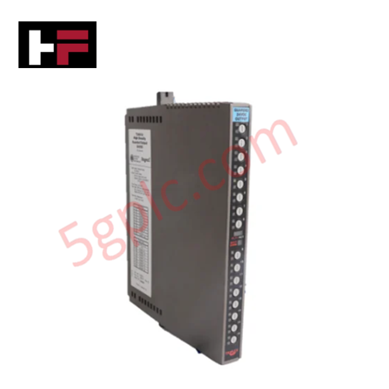
Configured for discrete signal output in safety-critical networks, the ICS Triplex T3481 (T3481 Guarded Output Module) provides direct physical and electrical execution. The module manages 16 channels of 24 VDC output, executing command signals while providing real-time load monitoring to ensure compliance with predefined safety logic states across the Trusted platform.
Hardware Specifications
| Parameter | Specification |
|---|---|
| Model | T3481 |
| Brand | ICS Triplex |
| Origin | United States |
| Weight | 1.82 kg |
| Dimensions | 3.2 cm x 26.5 cm x 35.8 cm |
| Operating Temp | Standard Industrial |
| Power Consumption | Configuration Dependent |
| Output Capacity | 16 Channels, 24 VDC |
SIS Triple Modular Redundancy (TMR) Architecture
The T3481 is designed to operate within a triple modular redundancy (TMR) 2oo3 architecture to facilitate fail-safe state execution. The module employs independent output drivers for each of the three internal channels, utilizing cross-channel comparison to detect and isolate discrepant output signals. Galvanic isolation is maintained at the interface level to decouple field-side transients from the internal safety bus, protecting the integrity of the voting logic and ensuring that the output state remains deterministic even in the event of an internal hardware failure.
Frequently Asked Questions
Q: Does the T3481 module support hot-swapping under load?
A: The T3481 is designed for hot-swap capability within the Trusted TMR chassis. To prevent unintended state changes, the safety controller must be set to a maintenance state for the associated I/O point before module extraction or insertion.
Q: How does the module handle fault detection for field-side output loops?
A: The module continuously monitors the field-side load current and output voltage. If the diagnostic circuit detects an open-circuit, short-circuit, or a mismatch between the internal commanded state and the actual field output, the fault is communicated to the TMR controller to trigger the designated safety response.
Field Installation Guidelines
- Ensure the chassis backplane is powered within the nominal range before module insertion to avoid high inrush currents.
- Align the T3481 module with the chassis guide rails and seat the backplane connector firmly, confirming mechanical engagement.
- Tighten the front-panel captive fasteners to establish a robust ground connection between the module housing and the chassis frame for effective EMI shielding.
- Verify that field wiring is terminated at the appropriate I/O interface blocks with correct polarity for the 24 VDC output loops.
- Perform a functional output loop verification using the engineering workstation to confirm that the programmed safety logic correctly drives the field devices.
Additional Information
- 100% Genuine Parts: All products are original and authentic, ensuring reliable industrial performance.
- 30-Day Refund Guarantee: Return any in-stock item within 30 days in original, unopened packaging for a full refund (excluding shipping and fees).
- 12-Month Warranty: Covers defects in materials or workmanship; excludes misuse, normal wear, or unauthorized modifications.
- Worldwide Shipping: We ship via USPS, UPS, FedEx, and DHL. Delivery times vary by country and may be subject to customs or import fees.
- Support & Contact: Technical and warranty assistance is available anytime. Contact us here: Contact.
- Purchase Guidance: Check product specifications and compatibility carefully before ordering to ensure proper application.
Tech & Buying Guide

Essential Motion Control Commands: A Practical Guide for Engineers
Automation engineers often rely on precise position and speed control to drive modern factory machinery. Modern industrial systems, such as Programmable Logic Controllers (PLCs) and Distributed Control Systems (DCS), depend heavily on standardized motion instructions. Mastering these commands ensures operational safety, protects mechanical components, and optimizes cycle times across production lines.

The Role of Intrinsic Safety Barriers in PLC and DCS Architectures
Implementing robust protection in hazardous industrial environments represents a fundamental safety requirement in factory automation. Process facilities often handle volatile gases, dusts, and chemical agents that pose significant combustion risks. Consequently, control system engineers must deploy energy-limiting interfaces to isolate safe-area control cabinets from hazardous-area field instrumentation. This article examines the function, selection, and electrical principles of intrinsic safety barriers within modern PLC and DCS networks.

Architectural Selection and Scale Classification of PLC Systems in Industrial Automation
Selecting the correct control platform represents a foundational engineering decision in factory automation. System designers must carefully balance technical parameters against long-term operational requirements when implementing a Programmable Logic Controller (PLC). This article examines the critical evaluation metrics, physical scale classifications, and operational architectures of modern control systems.