












Product Details
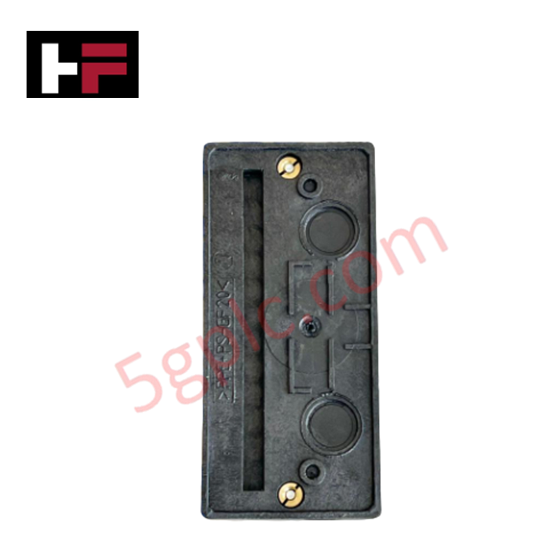
Configured for power distribution and input signal handling in Honeywell DCS platforms, the Honeywell 51309404-002 (51309404-002 Power/Input Board) provides direct physical/electrical execution. Interfacing directly with internal system backplanes, the module regulates power routing from system supplies to internal control electronics while managing incoming field signals across modular chassis assemblies. The board utilizes an industrial-grade backplane-mounted form factor to maintain continuous electrical connection within control rack environments.
Hardware Specifications
| Parameter | Specification |
|---|---|
| Model | 51309404-002 |
| Brand | Honeywell |
| Origin | USA |
| Weight | Approx. 0.60 kg (1.32 lbs) |
| Dimensions | Standard Modular Rack Card Profile |
| Operating Temp | 0 to 60 deg C |
| Power Consumption | Passive Power Distribution / Input Handling Assembly |
| System Compatibility | Honeywell Control Systems |
| Electrical Interface | Internal System Backplane |
| Mounting Type | Backplane-Mounted / Chassis Rack Mount |
4-20 mA HART Loop Protocol
The 51309404-002 power/input board supports digital signal routing across 4-20 mA HART loop protocol architectures without degrading analog current values. Onboard high-frequency filtering removes field-induced common-mode noise while allowing digital FSK (Frequency Shift Keying) HART communications to pass transparently to system controller cards. This enables continuous device diagnostics, range configuration, and primary variable conditioning directly through the backplane interface.
Frequently Asked Questions
Q: Does inserting the 51309404-002 board require shutting down the rack power supply?
A: Standard maintenance procedures require de-energizing the local rack rack section prior to module insertion to prevent transient power surges on internal backplane buses.
Q: How is ground continuity maintained across the backplane interface?
A: Grounding is established through low-impedance gold-plated edge connector pins that bond directly to the grounded metal chassis frame upon full insertion.
Q: What prevents mechanical misalignment during board installation?
A: Keyed backplane guide rails align the PCB edge connectors with internal rack slots, preventing inverted insertion or pin damage.
Field Installation Guidelines
- Disconnect system power from the targeted chassis rack prior to card installation or removal.
- Align the circuit board edges with the enclosure slot card guides.
- Slide the board into the rack until edge connectors fully seat into the backplane receptacle.
- Fasten top and bottom faceplate retention screws to secure the module against vibration.
- Ensure field input signal wiring shields are tied to the main cabinet grounding bus bar at a single termination point.
Additional Information
- 100% Genuine Parts: All products are original and authentic, ensuring reliable industrial performance.
- 30-Day Refund Guarantee: Return any in-stock item within 30 days in original, unopened packaging for a full refund (excluding shipping and fees).
- 12-Month Warranty: Covers defects in materials or workmanship; excludes misuse, normal wear, or unauthorized modifications.
- Worldwide Shipping: We ship via USPS, UPS, FedEx, and DHL. Delivery times vary by country and may be subject to customs or import fees.
- Support & Contact: Technical and warranty assistance is available anytime. Contact us here: Contact.
- Purchase Guidance: Check product specifications and compatibility carefully before ordering to ensure proper application.





Tech & Buying Guide

Redefining Control Systems: The Rise of Flexible I/O Modules in Industrial Automation
Conventional input-output architectures often limit engineering agility and inflate long-term inventory costs. Today, Flexible Input/Output Modules (FIOM) are transforming how control system engineers design, commission, and maintain automation infrastructure. By allowing individual channel software configuration, FIOM technology bridges the gap between rigid hardware design and dynamic plant requirements.

Understanding Modern SCADA Systems: Architecture, Communication Topologies, and Industrial Applications
Supervisory Control and Data Acquisition (SCADA) systems form the digital backbone of modern industrial automation. They collect critical field data, transmit signals across vast distances, and empower plant operators with real-time process visibility. Across modern infrastructures, SCADA solutions streamline centralized control and maintain continuous operational uptime.

Understanding OPC Servers in Modern Industrial Automation: Principles, Architecture, and Applications
In industrial automation, connecting physical hardware with high-level software remains a primary operational challenge. Factories utilize programmable logic controllers (PLCs), distributed control systems (DCS), human-machine interfaces (HMIs), and smart sensors from diverse vendors. These devices often speak different proprietary protocols. Open Platform Communications (OPC) servers solve this interoperability challenge by standardizing how data flows across factory networks.