


Product Details
Overview
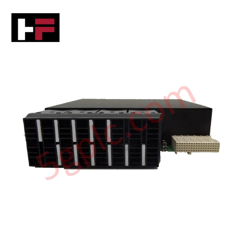
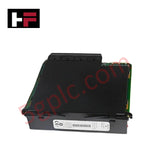
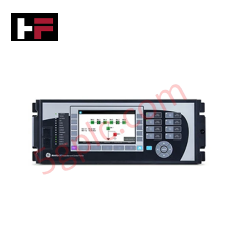
The GE UR8FH module is a dedicated CT/VT (Current Transformer/Voltage Transformer) unit designed for integration into the Multilin Universal Relay (UR) series. It provides precise current and voltage scaling for relay monitoring and control, ensuring accurate measurement and reliable system protection.
Technical Specifications
-
Manufacturer: General Electric Multilin
-
Manufacturing Location: Markham, Ontario, Canada
-
Model: UR8FH
-
Type: CT/VT Module
-
Weight: 2 lb 9 oz (approx. 1.17 kg)
-
Dimensions: 15 cm (L) × 18 cm (W) × 4 cm (H)
Key Features
-
Current Transformers (CT):
-
Three phase CTs supporting 1 A / 5 A inputs
-
Dedicated ground CT supporting 1 A / 5 A inputs
-
Voltage Transformers (VT):
-
Four VT input terminals
-
Scales down voltage and current for safe relay monitoring and control
-
Channel Configuration:
-
Channels 1 and 5: Phase A
-
Channels 2 and 6: Phase B
-
Channels 3 and 7: Phase C
-
Channels 4 and 8: Ground or neutral reference
-
Safety and Installation:
-
Nominal current rating (1 A or 5 A) must match the CT secondary rating
-
Incorrect installation may result in equipment damage
Applications
-
Power system monitoring and protection
-
Relay-based current and voltage measurement
-
Industrial automation requiring CT/VT scaling
-
Expansion of UR relay functionality for advanced grid control
FAQ
-
Q: What is the maximum current rating supported? A: The module supports CT inputs rated at 1 A or 5 A, depending on the connected transformer.
-
Q: Can the UR8FH be used with both CT and VT simultaneously? A: Yes, the module is designed to handle both current and voltage transformer inputs for comprehensive relay monitoring.
-
Q: How should installation be performed? A: Follow the UR series manuals carefully, ensuring CT secondary ratings match the module’s nominal input rating.
Additional Information
- 100% Genuine Parts: All products are original and authentic, ensuring reliable industrial performance.
- 30-Day Refund Guarantee: Return any in-stock item within 30 days in original, unopened packaging for a full refund (excluding shipping and fees).
- 12-Month Warranty: Covers defects in materials or workmanship; excludes misuse, normal wear, or unauthorized modifications.
- Worldwide Shipping: We ship via USPS, UPS, FedEx, and DHL. Delivery times vary by country and may be subject to customs or import fees.
- Support & Contact: Technical and warranty assistance is available anytime. Contact us here: Contact.
- Purchase Guidance: Check product specifications and compatibility carefully before ordering to ensure proper application.


Tech & Buying Guide

Understanding Dry Contacts in PLC Wiring: An Industrial Automation Guide
Mastering contact switching principles is essential for reliable control panels. Field devices and PLCs interface through dry or wet contacts. This technical guide examines the mechanics of dry contacts, explores their wiring architectures, and evaluates their key advantages in industrial automation.

Ultimate Commissioning Checklist for Industrial Automation Systems: An Engineering Guide
Commissioning is the most decisive phase of an industrial automation project, transforming control hardware and software into an operational facility. Thorough testing prevents costly startup delays and builds customer confidence. This guide covers essential checklists, electrical standards, and best practices.

Redundant Automation Systems: Core Architecture, Business Value, and Technical Advantages
Unplanned downtime poses a major financial threat to process manufacturing. To prevent costly interruptions, engineers deploy redundant PLC and DCS architectures that ensure continuous operation when hardware fails. This technical guide explores redundancy principles, critical system nodes, and real-world scenarios.