


Product Details
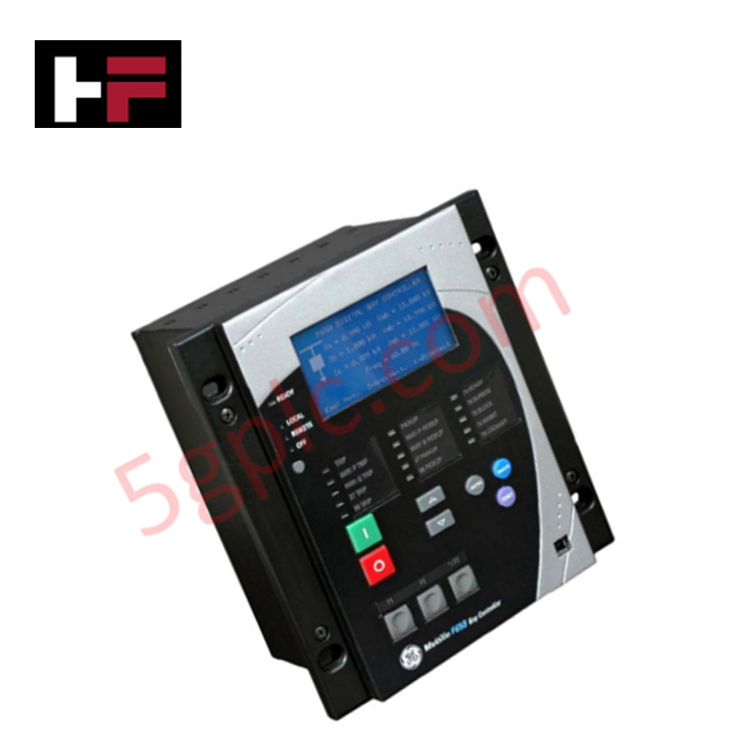
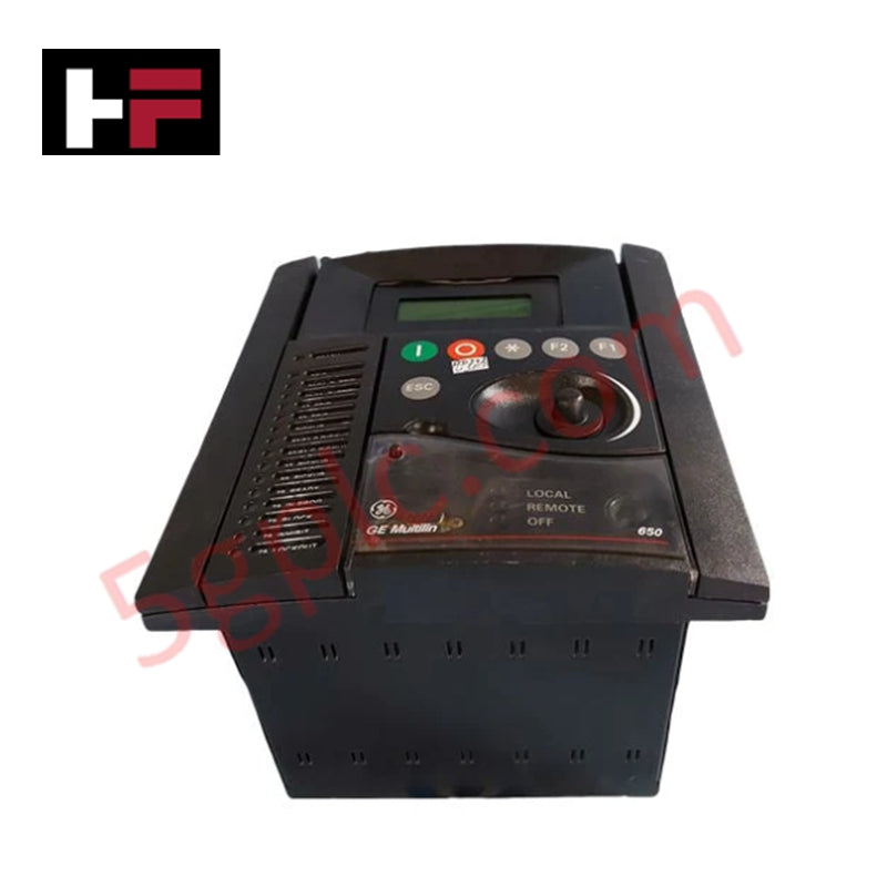
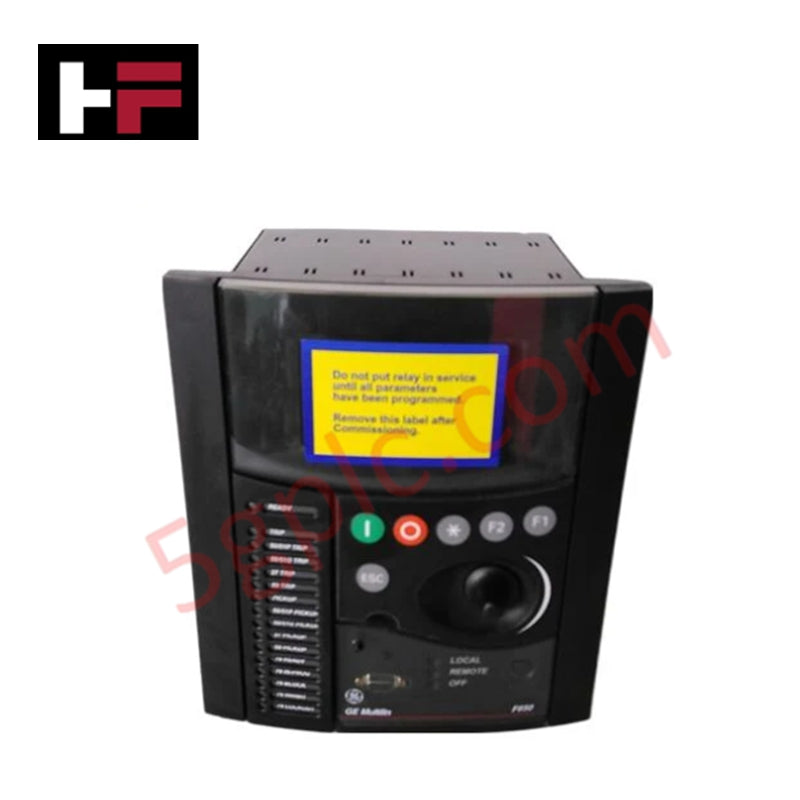
Configured for feeder protection and substation automation, the GE Multilin F650BABF1GOHLO (F650 Digital Bay Controller) provides direct physical/electrical execution of overcurrent monitoring, breaker control, and automated power management logic.
Hardware Specifications
| Parameter | Specification |
|---|---|
| Model | F650BABF1GOHLO |
| Brand | GE Multilin |
| Weight | 0.7 kg |
| Dimensions | 120 mm x 120 mm x 95 mm |
| Operating Temp | -40 to 70 deg C |
| Power Consumption | 30 W |
| Power Supply | 110-250 VAC/VDC |
| Protection Class | IP20 |
Industrial Control Deterministic Network
The F650BABF1GOHLO functions as a localized controller within distribution systems, requiring precise synchronization with the station bus. To maintain deterministic performance, backplane bus communication velocity must be configured to match the latency requirements of the host SCADA system. Firmware flash compatibility is restricted to supported GE Multilin versions; verify that the internal logic registers are correctly mapped before deploying site-specific protection settings. The integration of I/O density scaling allows this controller to manage localized load shedding and restoration sequences. Ensure that network communication protocols are correctly initialized during setup to prevent data packet collisions, which can delay the execution of time-critical breaker control signals.
Frequently Asked Questions
Q: Does the unit support hot-swapping of the logic controller module?
A: No. The F650BABF1GOHLO does not support hot-swapping. The unit must be isolated from the auxiliary power supply and all sensing inputs before any maintenance or module removal is performed to prevent electrical hazards and loss of register data.
Q: How can the protection logic be verified without interrupting the primary power flow?
A: The controller supports secondary injection testing via the designated terminal inputs. Protection elements such as overcurrent and undervoltage thresholds can be validated by injecting controlled test currents and voltages, allowing for logic verification without de-energizing the primary distribution feeder.
Field Installation Guidelines
- Physical Mounting: Install the unit in a clean, dry environment consistent with its IP20 rating. Ensure the 120 x 120 mm panel cutout is deburred to prevent stress on the controller housing during installation.
- Grounding: Terminate the chassis ground terminal to the local equipment grounding bus using a dedicated low-impedance conductor. This path is necessary for transient surge dissipation.
- Electrical Termination: Verify the auxiliary power supply input (110-250 VAC/VDC) before energization. Ensure all current transformer (CT) and potential transformer (PT) leads are securely terminated and properly phased to prevent incorrect directional protection response.
- Communication Wiring: Use shielded, twisted-pair cabling for all industrial communication protocols. Ensure cable shields are terminated at the designated ground lug on the controller backplane to minimize the risk of electromagnetic interference.
Additional Information
- 100% Genuine Parts: All products are original and authentic, ensuring reliable industrial performance.
- 30-Day Refund Guarantee: Return any in-stock item within 30 days in original, unopened packaging for a full refund (excluding shipping and fees).
- 12-Month Warranty: Covers defects in materials or workmanship; excludes misuse, normal wear, or unauthorized modifications.
- Worldwide Shipping: We ship via USPS, UPS, FedEx, and DHL. Delivery times vary by country and may be subject to customs or import fees.
- Support & Contact: Technical and warranty assistance is available anytime. Contact us here: Contact.
- Purchase Guidance: Check product specifications and compatibility carefully before ordering to ensure proper application.


Tech & Buying Guide

Essential SCADA Features for Modern IoT-Enabled Industrial Automation
The convergence of traditional SCADA systems with the Industrial Internet of Things (IIoT) has redefined factory automation. Choosing a robust platform requires more than just standard monitoring capabilities. In this era of Industry 4.0, your supervisory system must bridge the gap between legacy control systems and enterprise-level data integration.

Selecting Rockwell Automation Allen-Bradley PLCs for Small and Mid-Sized Applications
Rockwell Automation remains a cornerstone in global industrial automation. Their Allen-Bradley brand provides a comprehensive portfolio of control systems designed to meet diverse production requirements. Choosing the right programmable logic controller (PLC) is critical for system reliability and scalability. This guide analyzes the Micro and Compact Logix families to help you select the optimal solution for small and medium-scale projects.

Strategic Selection: Choosing the Right SCADA Software for Your PLC Project
In industrial automation, the SCADA (Supervisory Control and Data Acquisition) system acts as the bridge between raw machine data and actionable human intelligence. Selecting the incorrect software platform can lead to integration bottlenecks, scalability issues, and excessive long-term maintenance costs. As an automation consultant with 15 years of experience, I have guided many projects through the selection process. Below are the essential criteria for choosing a platform that ensures both performance and longevity.