


Product Details
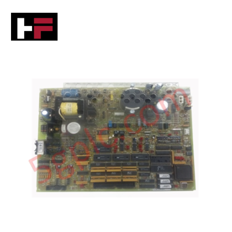
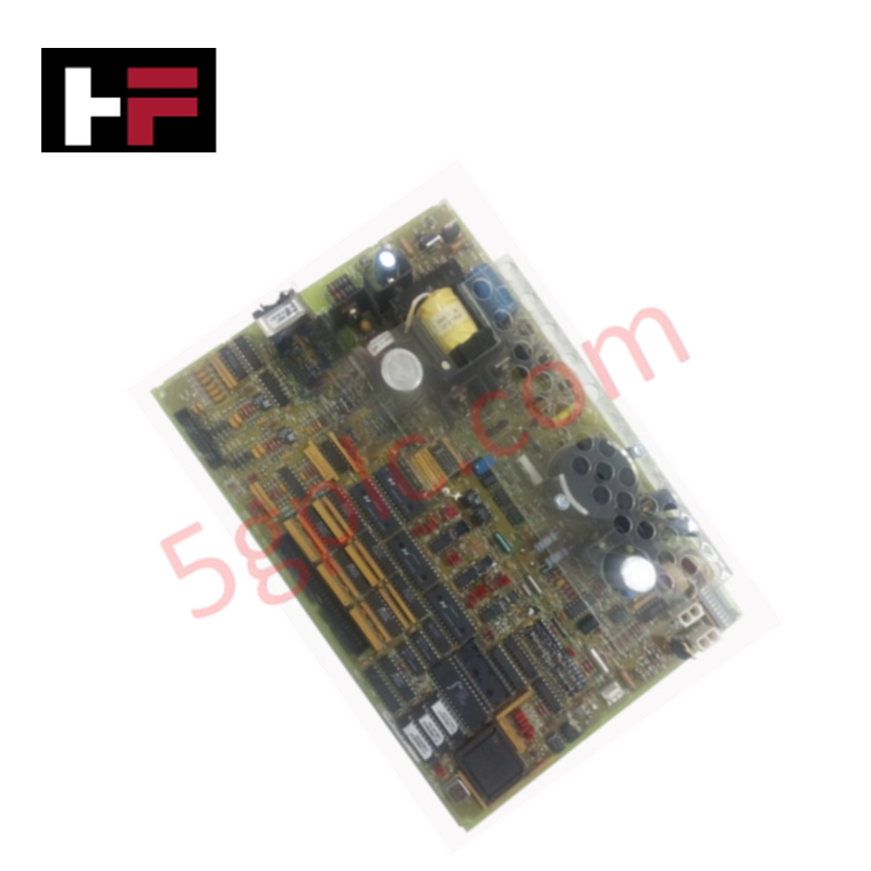
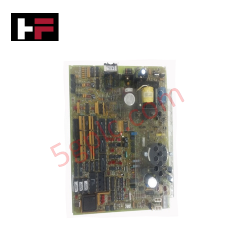
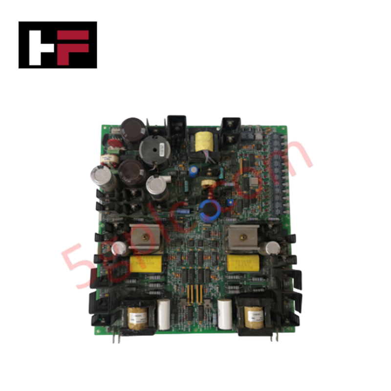
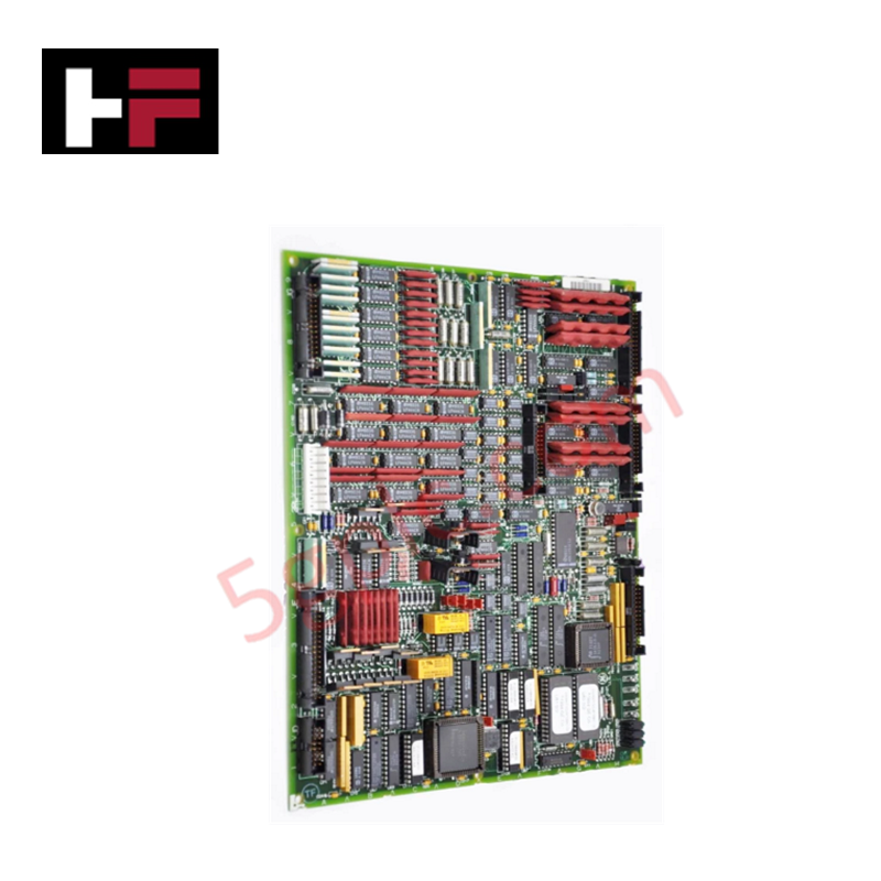
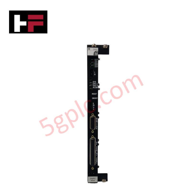
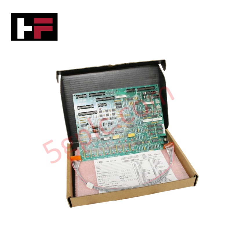
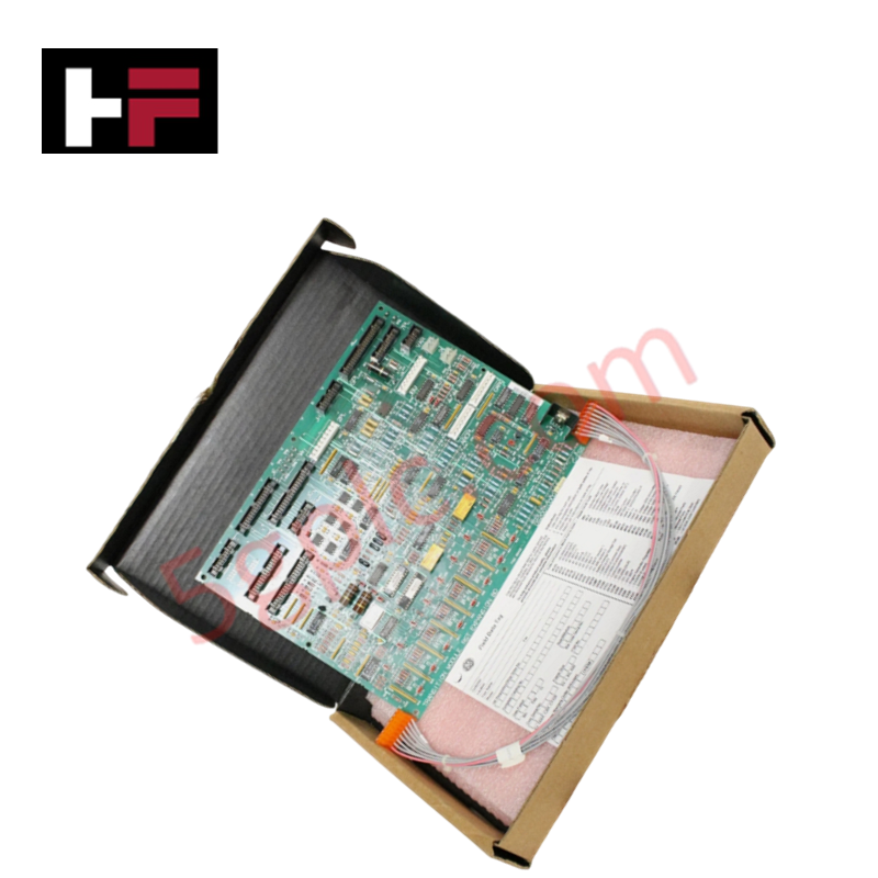
Configured for rotational frequency monitoring and flame detection within Mark V Speedtronic systems, the GE DS200TCEAG1B (DS200TCEA Emergency Over Speed Board) provides direct physical/electrical execution of safety-critical turbine trip logic.
Hardware Specifications
| Parameter | Specification |
|---|---|
| Model | DS200TCEAG1B |
| Brand | General Electric |
| Origin | USA |
| Weight | Not specified |
| Dimensions | Standard Mark V PCB footprint |
| Operating Temp | Per Mark V environmental standards |
| Power Consumption | Backplane rail supply |
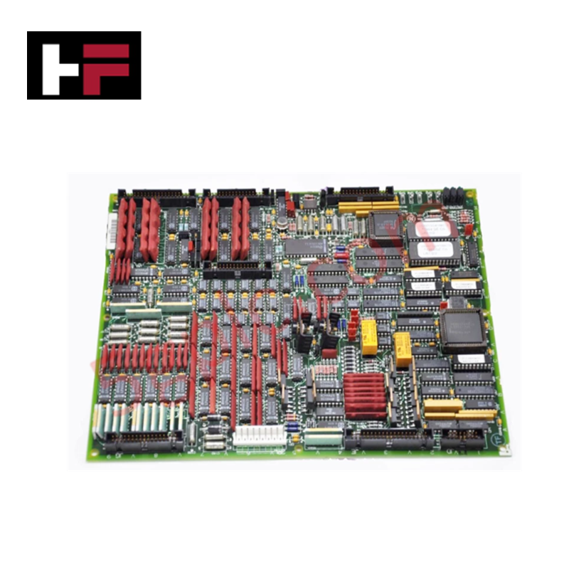
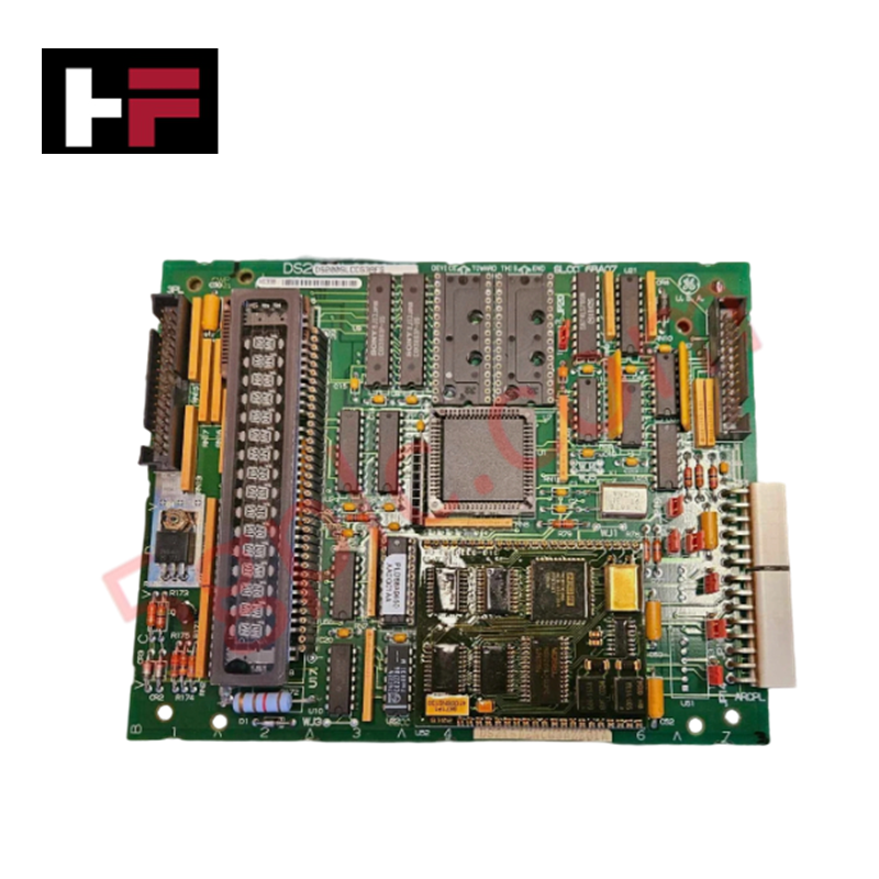
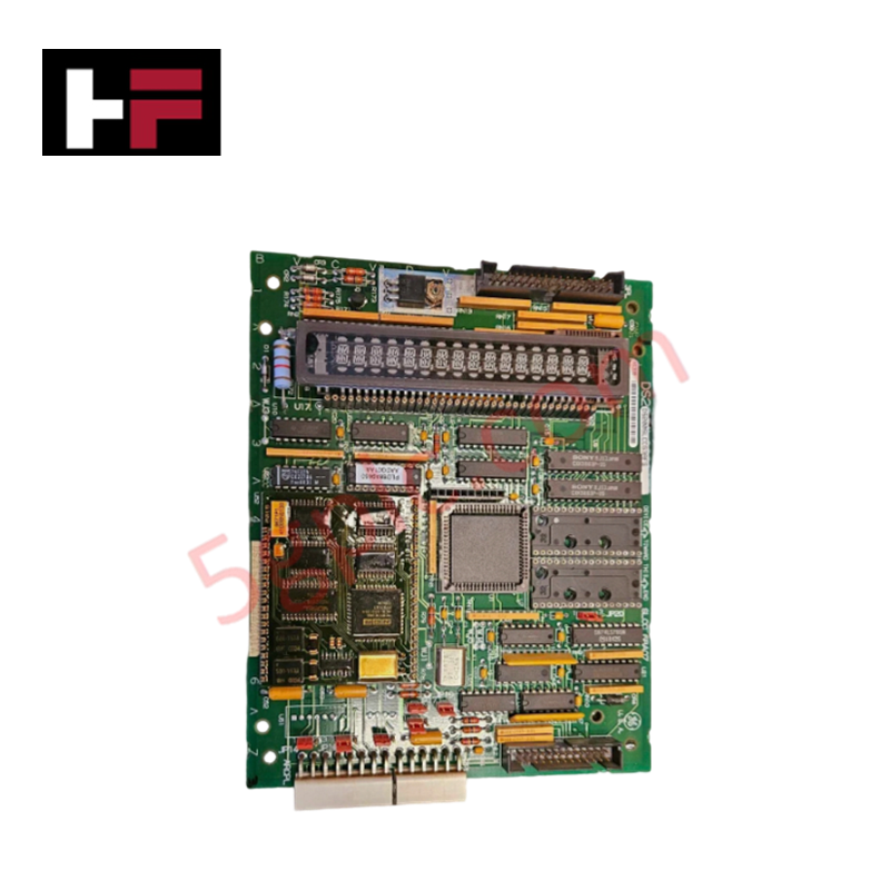
| Components | 1 x microprocessor, 3 x fuses, 30 x jumpers |
| Connectors | 2 x bayonet interface connections |
Industrial Control and Firmware Compatibility
The DS200TCEAG1B utilizes a microprocessor-based architecture to process turbine speed inputs and flame detection signals. Firmware flash compatibility is achieved via the population of PROM modules, which must be transferred from the existing board to ensure functional continuity. Deterministic network performance is maintained through the board's integration with the protection core, where it interfaces with speed sensors to trigger rapid shutdown sequences. I/O density scaling is managed by the rack's backplane, ensuring that over-speed trip thresholds are communicated in real-time to the main processor, provided the firmware and hardware jumper settings are correctly aligned.
Frequently Asked Questions
Q: Does the replacement board include pre-installed PROM modules?
A: No. The board is shipped unpopulated. Users must transplant the existing PROM modules from the legacy board to the new assembly. Ensure all modules are seated correctly in their respective sockets.
Q: What is the function of the 30 onboard jumpers?
A: The jumpers are used to define specific protection logic thresholds and hardware address mapping. These must be set to match the original board's configuration to maintain existing system safety logic.
Field Installation Guidelines
- Static Discharge Precautions: The internal memory modules are highly sensitive to electrostatic discharge. Always utilize a grounded anti-static wrist strap during all handling and PROM module transfer procedures.
- Bayonet Connector Handling: When removing or installing bayonet connectors, stabilize the board with one hand while manipulating the connector with the other. This prevents excessive bending stress on the PCB and minimizes the risk of solder joint fatigue.
- Fuse Verification: Prior to system power-up, check the 3 onboard fuses for continuity. Replace any blown fuses with identical ratings to ensure protection circuitry is active.
- Component Seating: Inspect all cable interface points for debris or oxidation. Ensure bayonet connectors are fully locked to prevent signal intermittency, which could lead to unintended turbine trip events.
- Jumper Verification: Compare the jumper positions on the replacement board against the legacy board. Confirm that all settings adhere to the site-specific turbine control documentation before system commissioning.
Additional Information
- 100% Genuine Parts: All products are original and authentic, ensuring reliable industrial performance.
- 30-Day Refund Guarantee: Return any in-stock item within 30 days in original, unopened packaging for a full refund (excluding shipping and fees).
- 12-Month Warranty: Covers defects in materials or workmanship; excludes misuse, normal wear, or unauthorized modifications.
- Worldwide Shipping: We ship via USPS, UPS, FedEx, and DHL. Delivery times vary by country and may be subject to customs or import fees.
- Support & Contact: Technical and warranty assistance is available anytime. Contact us here: Contact.
- Purchase Guidance: Check product specifications and compatibility carefully before ordering to ensure proper application.
Tech & Buying Guide

Essential SCADA Features for Modern IoT-Enabled Industrial Automation
The convergence of traditional SCADA systems with the Industrial Internet of Things (IIoT) has redefined factory automation. Choosing a robust platform requires more than just standard monitoring capabilities. In this era of Industry 4.0, your supervisory system must bridge the gap between legacy control systems and enterprise-level data integration.

Selecting Rockwell Automation Allen-Bradley PLCs for Small and Mid-Sized Applications
Rockwell Automation remains a cornerstone in global industrial automation. Their Allen-Bradley brand provides a comprehensive portfolio of control systems designed to meet diverse production requirements. Choosing the right programmable logic controller (PLC) is critical for system reliability and scalability. This guide analyzes the Micro and Compact Logix families to help you select the optimal solution for small and medium-scale projects.

Strategic Selection: Choosing the Right SCADA Software for Your PLC Project
In industrial automation, the SCADA (Supervisory Control and Data Acquisition) system acts as the bridge between raw machine data and actionable human intelligence. Selecting the incorrect software platform can lead to integration bottlenecks, scalability issues, and excessive long-term maintenance costs. As an automation consultant with 15 years of experience, I have guided many projects through the selection process. Below are the essential criteria for choosing a platform that ensures both performance and longevity.