


Product Details
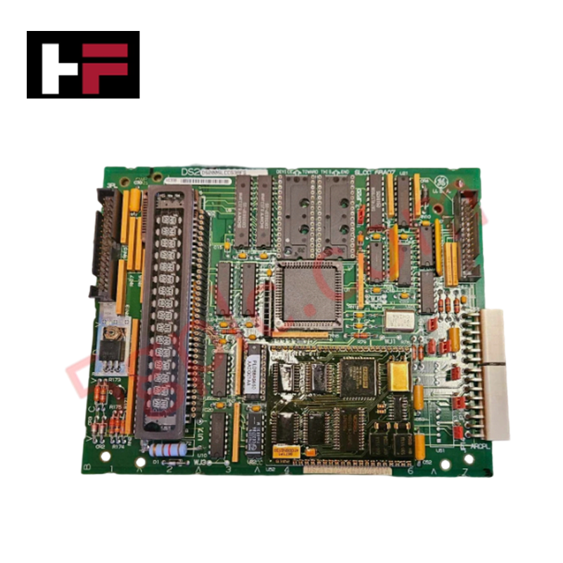
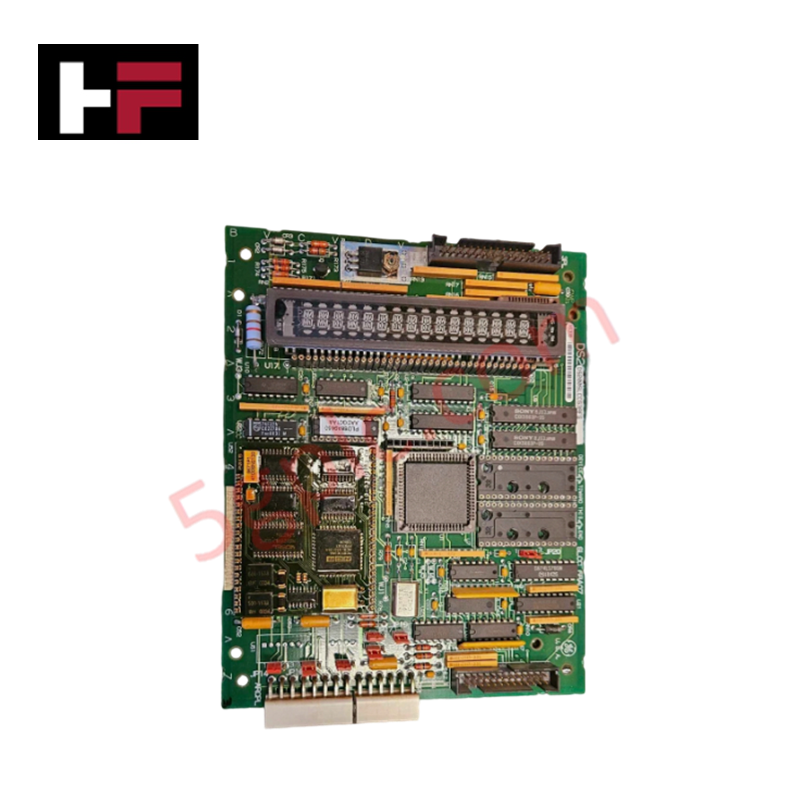
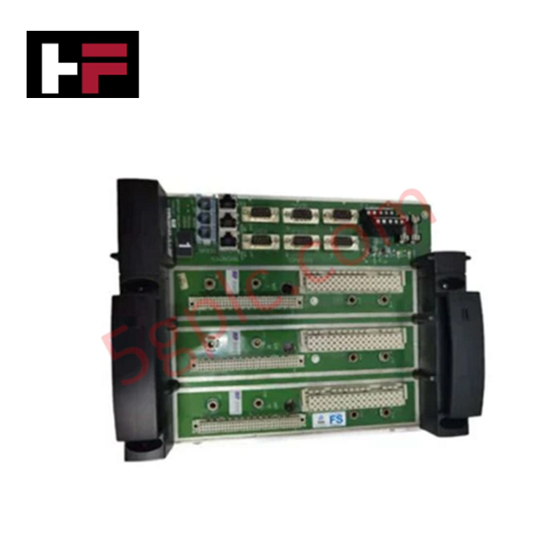
Configured for high-speed network integration within Mark V and EX2000 control platforms, the GE DS200SLCCG3A (DS200SLCC LAN Communication Card) provides direct physical/electrical execution of LAN-based controller communication.
Hardware Specifications
| Parameter | Specification |
|---|---|
| Model | DS200SLCCG3A |
| Brand | General Electric |
| Origin | USA |
| Dimensions | Standard Mark V PCB footprint |
| Operating Temp | Per Mark V environmental standards |
| Power Consumption | Backplane rail supply |
| Processor | LAN Control Processor (U1) |
| Interface | 16-position alphanumeric display |
Industrial Control and Firmware Compatibility
The DS200SLCCG3A facilitates deterministic data exchange across the Mark V backplane. Proper operation is contingent upon backplane bus communication velocity settings that synchronize the LAN control processor with the driver controller processor (DCP) on the SDCC board. Firmware flash compatibility is managed via replaceable EPROMS (U6, U7), which house the LCP software stack. Any replacement of these memory modules requires strict adherence to checksum validation to ensure data integrity during LCP execution. I/O density scaling is supported through the board's dual-ported RAM (U5) architecture, which regulates the data handshaking between the LAN controller and host drive electronics.
Frequently Asked Questions
Q: How is the LCP software updated on the SLCC board?
A: The LCP software is stored in replaceable EPROMS located at U6 and U7. To update, remove the board, extract the existing EPROMS, and install the new programmed EPROMS into the designated sockets while observing static discharge precautions.
Q: What is the purpose of the connector labeled KPPL?
A: The KPPL connector serves as the interface for the programmer module. This module allows operators to perform diagnostic testing, adjust software parameters, and view fault codes via the 16-position alphanumeric display.
Field Installation Guidelines
- Static Sensitivity: The SLCC board utilizes sensitive CMOS components. Always wear a grounded anti-static wrist strap when handling the PCB to prevent permanent damage to the LCP or memory modules.
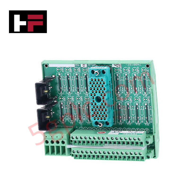
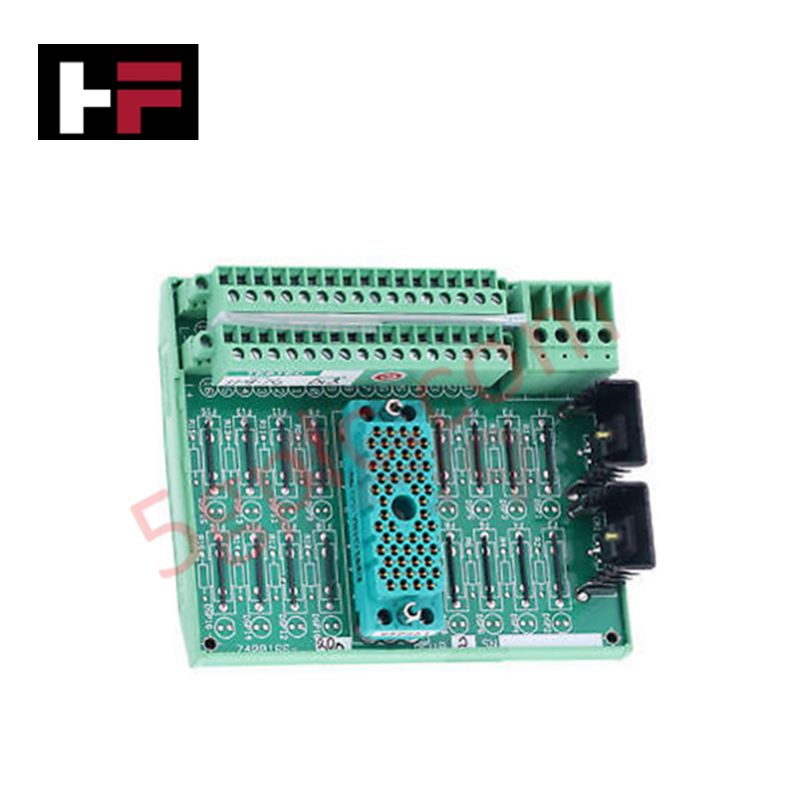
- Connector Alignment: Ensure all system-level connections to the NTB/3TB, SDCC, and TCCB boards via the 2PL connector are fully seated. Improper seating of the 2PL or 3PL connectors can cause communication timeouts between the LCP and the SDCC.
- Programmer Module: When mounting the programmer module onto the KPPL connector, apply uniform pressure to ensure the pins are correctly aligned and fully engaged to prevent intermittent diagnostic data.
- Component Verification: Before energizing the cabinet, verify that EPROMS U6 and U7 are oriented correctly according to the notch index on the socket. Reverse installation will result in immediate boot-up failure.
- Grounding: Ensure the board is properly secured to the cabinet chassis via its mounting screws to maintain the integrity of the isolated and non-isolated circuit grounding paths.
Additional Information
- 100% Genuine Parts: All products are original and authentic, ensuring reliable industrial performance.
- 30-Day Refund Guarantee: Return any in-stock item within 30 days in original, unopened packaging for a full refund (excluding shipping and fees).
- 12-Month Warranty: Covers defects in materials or workmanship; excludes misuse, normal wear, or unauthorized modifications.
- Worldwide Shipping: We ship via USPS, UPS, FedEx, and DHL. Delivery times vary by country and may be subject to customs or import fees.
- Support & Contact: Technical and warranty assistance is available anytime. Contact us here: Contact.
- Purchase Guidance: Check product specifications and compatibility carefully before ordering to ensure proper application.
Tech & Buying Guide

Essential SCADA Features for Modern IoT-Enabled Industrial Automation
The convergence of traditional SCADA systems with the Industrial Internet of Things (IIoT) has redefined factory automation. Choosing a robust platform requires more than just standard monitoring capabilities. In this era of Industry 4.0, your supervisory system must bridge the gap between legacy control systems and enterprise-level data integration.

Selecting Rockwell Automation Allen-Bradley PLCs for Small and Mid-Sized Applications
Rockwell Automation remains a cornerstone in global industrial automation. Their Allen-Bradley brand provides a comprehensive portfolio of control systems designed to meet diverse production requirements. Choosing the right programmable logic controller (PLC) is critical for system reliability and scalability. This guide analyzes the Micro and Compact Logix families to help you select the optimal solution for small and medium-scale projects.

Strategic Selection: Choosing the Right SCADA Software for Your PLC Project
In industrial automation, the SCADA (Supervisory Control and Data Acquisition) system acts as the bridge between raw machine data and actionable human intelligence. Selecting the incorrect software platform can lead to integration bottlenecks, scalability issues, and excessive long-term maintenance costs. As an automation consultant with 15 years of experience, I have guided many projects through the selection process. Below are the essential criteria for choosing a platform that ensures both performance and longevity.