


Product Details
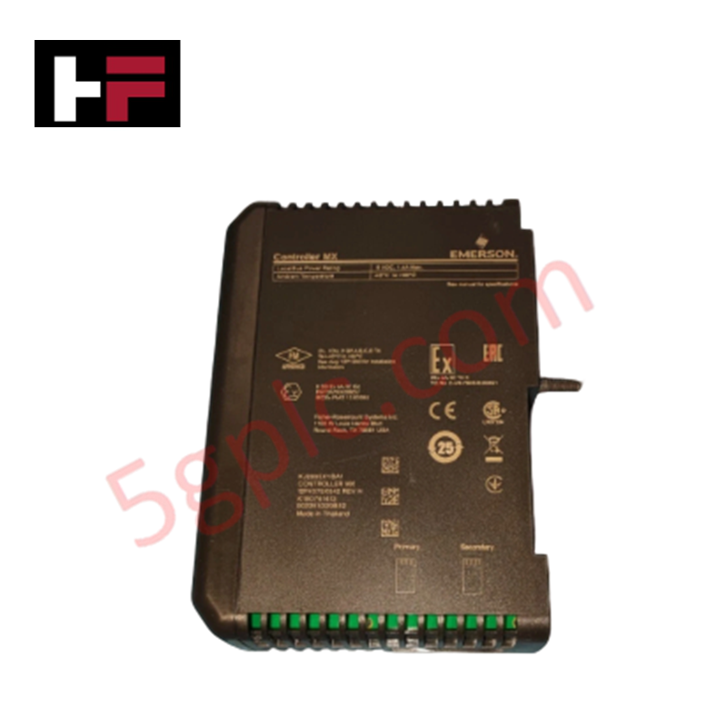
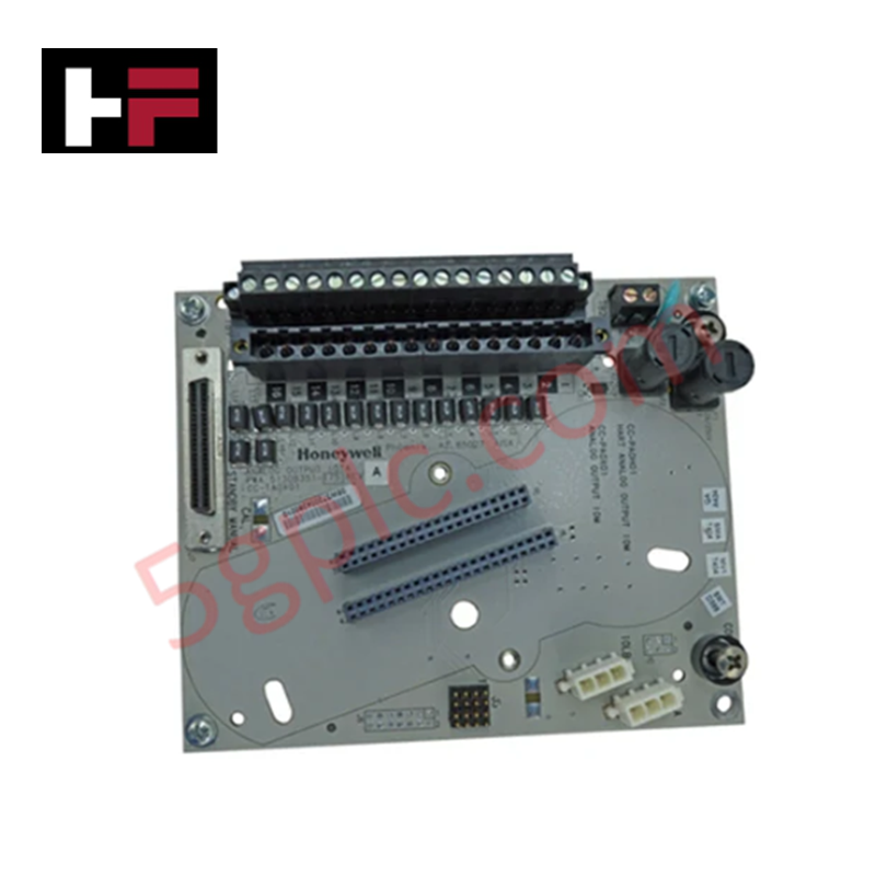
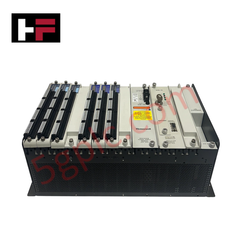
The Emerson KJ2003X1-PW1, also cataloged as the KJ2003X1-PW1 Redundant SLS Controller Module, operates as a dedicated hardware component for safety logic execution within DeltaV distributed control system networks. The module processes discrete and analog field variables routed through local safety instrumented sub-buses, running designated interlock equations to govern the physical state of safety-critical elements independent of standard control loops.
Hardware Specifications
| Parameter | Specification |
| Model | KJ2003X1-PW1 |
| Brand | Emerson |
| Origin | USA |
| Weight | 2 kg |
| Dimensions | 30 x 20 x 20 cm |
| Operating Temp | -40 deg C to +70 deg C |
| Power Consumption | Standard local bus loading footprint |
| Subsystem Class | Redundant Safety Logic Solver (SLS) |
| Mounting Orientation | DIN rail assembly |
Process Loop Integration and Channel Isolation
Mechanical execution of this safety logic solver utilizes internal electrical partitioning to secure synchronized backup monitoring lines. The processor pathways execute continuous channel-to-channel isolation metrics across integrated fieldbus links, blocking voltage spikes or common-mode ground loops from skewing active 4-20 mA HART loop protocol parameters. This hardware boundary protects internal logic calculation registers, ensuring steady serial data verification during parallel cross-processor communication scanning cycles.
Frequently Asked Questions
Q: How is the redundant fail-over switching delay managed within this hardware layout?
A: The module architecture uses a dedicated hardware synchronization line to replicate runtime logic registers. If the active unit loses input power or suffers a internal diagnostic fault, the backup partner handles logic execution with a zero-millisecond data tracking delay.
Q: Does this hardware assembly support online hot-swap procedures during processing operations?
A: Yes. In a redundant configuration, a faulted card can undergo hot-swap removal and replacement while the platform remains energized. The remaining partner executes active safety tasks continuously without shifting the final control elements to a tripped state.
Field Installation Guidelines
-
DIN Rail Attachment Protocol: Position the housing base over the standardized industrial metal rail. Apply uniform force perpendicular to the mounting plane until the rear grounding springs and physical retention clamps click completely into position.
-
Redundant Power Line Routing: Connect the independent incoming supply lines into separate terminal block positions. Ensure all wire connections match torque requirements to eliminate high contact resistance across supply paths.
-
Shield Matrix Ground Termination: Land all external field transmission and network loop shield drains at the central enclosure master earth bus bar. Correct single-point grounding methods block inductive common-mode noise from destabilizing serial processing.
-
Enclosure Clearance and Convection: Maintain the specified physical gaps above and below the module housing inside the cabinet to prevent thermal stagnation, keeping the ambient climate within the allowed -40 deg C to +70 deg C limits.
Additional Information
- 100% Genuine Parts: All products are original and authentic, ensuring reliable industrial performance.
- 30-Day Refund Guarantee: Return any in-stock item within 30 days in original, unopened packaging for a full refund (excluding shipping and fees).
- 12-Month Warranty: Covers defects in materials or workmanship; excludes misuse, normal wear, or unauthorized modifications.
- Worldwide Shipping: We ship via USPS, UPS, FedEx, and DHL. Delivery times vary by country and may be subject to customs or import fees.
- Support & Contact: Technical and warranty assistance is available anytime. Contact us here: Contact.
- Purchase Guidance: Check product specifications and compatibility carefully before ordering to ensure proper application.
Tech & Buying Guide

Navigating Industrial Automation Failures: Types, Causes, and Mitigation Strategies
Modern manufacturing relies heavily on automated control systems to maximize throughput and maintain product quality. However, unplanned downtime in industrial automation can cost facility operators thousands of dollars per hour. Understanding how programmable logic controllers (PLCs), distributed control systems (DCS), and field instrumentation fail empowers engineering teams to implement robust preventive maintenance strategies.

Essential Motion Control Commands: A Practical Guide for Engineers
Automation engineers often rely on precise position and speed control to drive modern factory machinery. Modern industrial systems, such as Programmable Logic Controllers (PLCs) and Distributed Control Systems (DCS), depend heavily on standardized motion instructions. Mastering these commands ensures operational safety, protects mechanical components, and optimizes cycle times across production lines.

The Role of Intrinsic Safety Barriers in PLC and DCS Architectures
Implementing robust protection in hazardous industrial environments represents a fundamental safety requirement in factory automation. Process facilities often handle volatile gases, dusts, and chemical agents that pose significant combustion risks. Consequently, control system engineers must deploy energy-limiting interfaces to isolate safe-area control cabinets from hazardous-area field instrumentation. This article examines the function, selection, and electrical principles of intrinsic safety barriers within modern PLC and DCS networks.