










Product Details
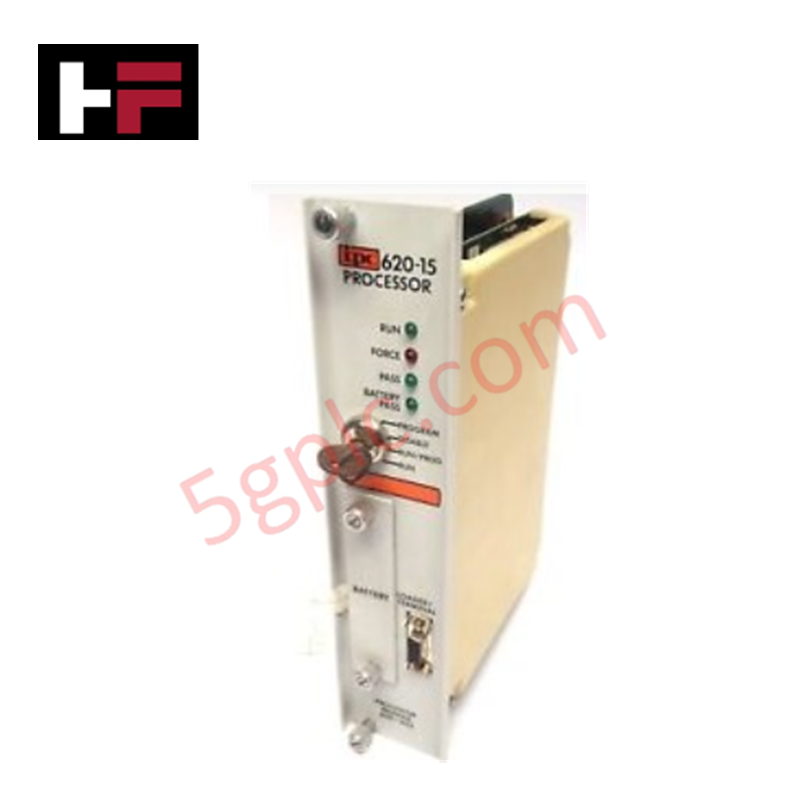
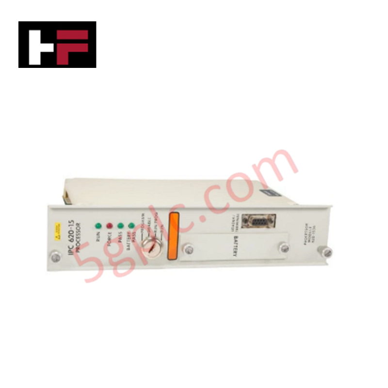
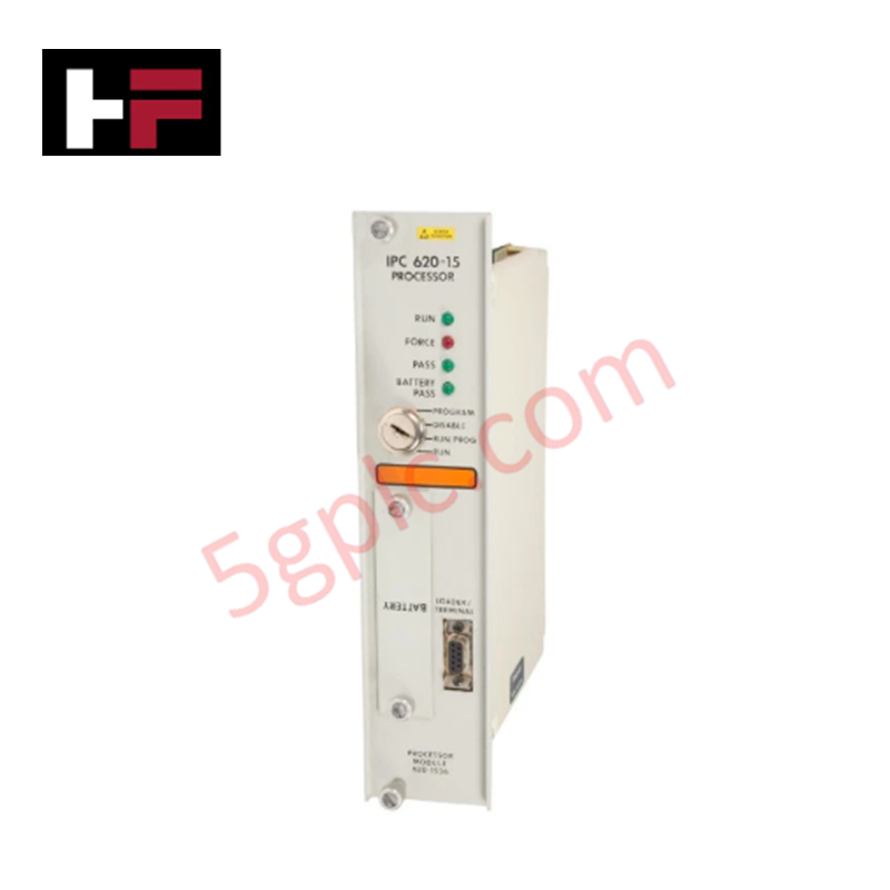
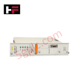
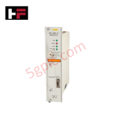
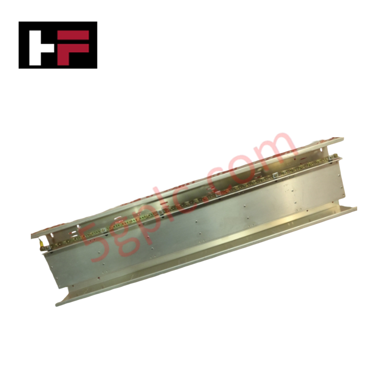
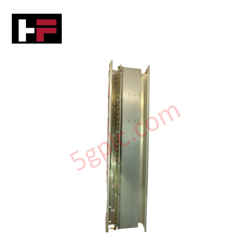
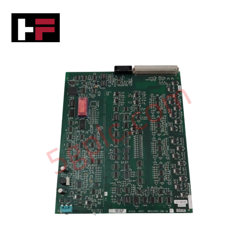
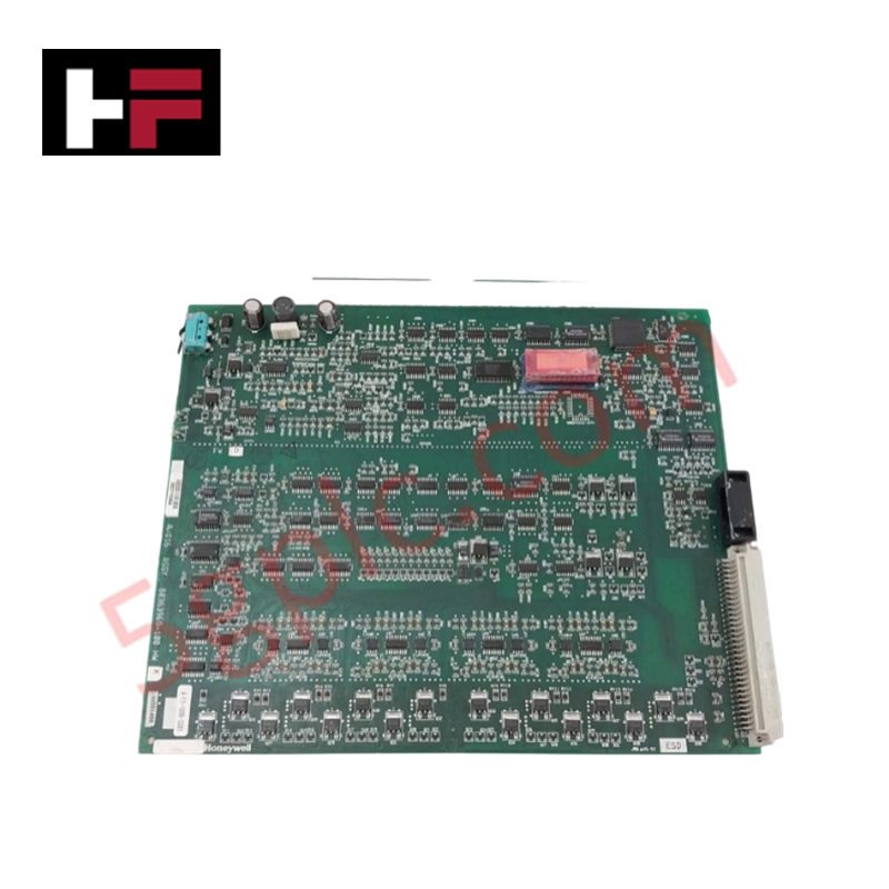
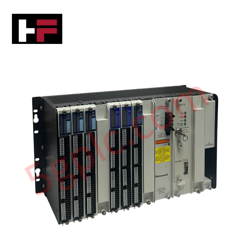
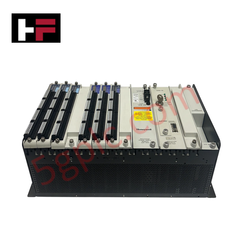
The Honeywell 620-1536, also cataloged as the 620-15 Processor Module, operates as a dedicated hardware component for programmable logic execution and communication routing within Honeywell IPC 620 rack platforms. It executes user logic scans, drives local backplane data exchange, and communicates via a 9-pin Sub-D connector interface with diagnostic status displayed through front-panel LEDs.
Hardware Specifications
| Parameter | Specification |
|---|---|
| Model | 620-1536 |
| Brand | Honeywell |
| Origin | USA |
| Weight | 1.18 kg (2.60 lbs) |
| Dimensions | Standard IPC 620 Chassis Slot |
| Operating Temp | 0 deg C to 60 deg C |
| Power Consumption | 12 W (Internal Backplane Bus) |
| Diagnostic Display | Front Panel Status LEDs |
| Communication Interface | 9-pin Sub-D Serial Port |
| System Compatibility | Honeywell IPC 620 System |
Channel-to-Channel Isolation and Loop Protocol Response
The Honeywell 620-1536 processor module utilizes internal optocouplers to maintain galvanic isolation between primary processing logic and external serial communication lines. This isolation suppresses common-mode ground loops and protects internal registers during serial data transfers over 4-20 mA HART loops and networked field instrumentation adapters. The module continuously executes parity checking and loop verification protocols to ensure reliable data throughput across connected control segments.
Frequently Asked Questions
Q: Can the 620-1536 processor module be hot-swapped while the rack backplane is energized?
A: No. Primary rack power must be completely shut down prior to installing or removing the module to prevent electrical transients and data corruption on the backplane bus.
Q: What is the primary function of the front-panel status LEDs?
A: The LEDs provide direct hardware diagnostics, indicating CPU operational state, logic execution status, memory integrity, and serial communication activity on the 9-pin Sub-D port.
Field Installation Guidelines
- Turn off all main power sources to the IPC 620 chassis before inserting the processor module into its slot.
- Align the module circuit board with the chassis card guides and slide it in until the rear pin header seats completely into the backplane.
- Tighten the top and bottom panel securing screws to establish a firm chassis ground connection.
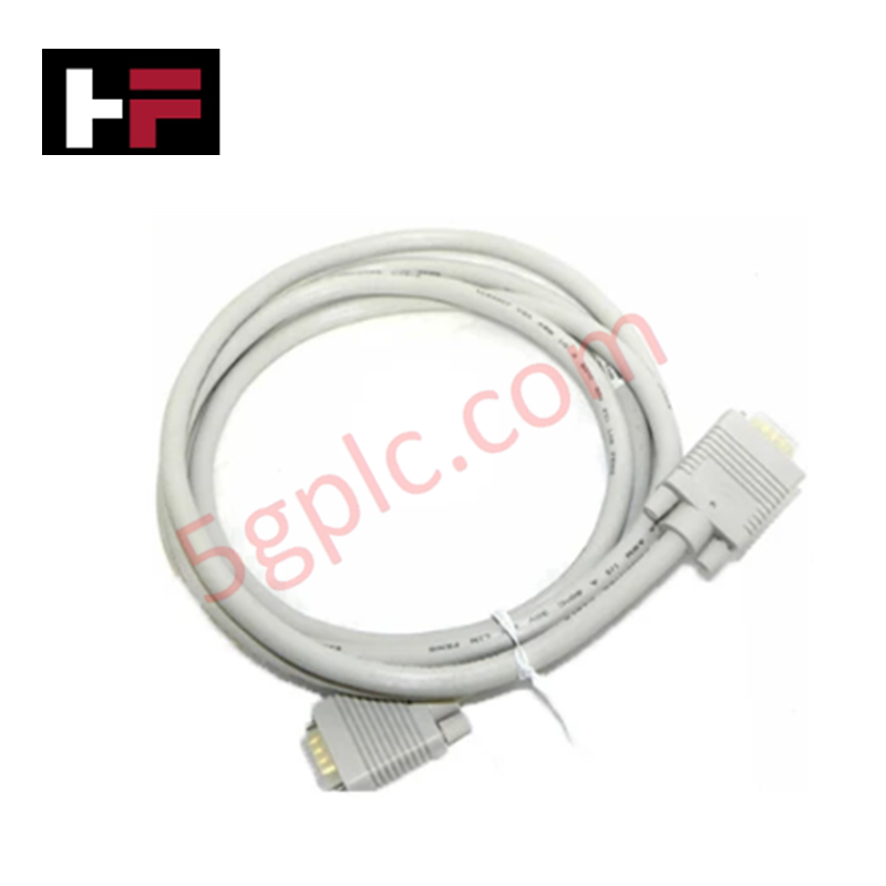
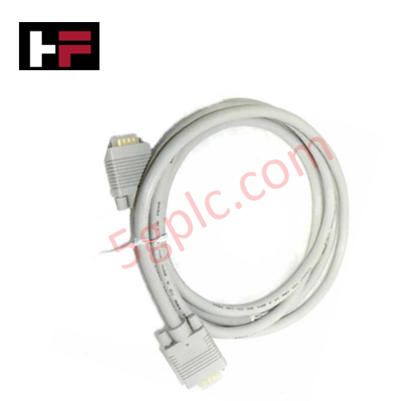
- Attach the 9-pin Sub-D communication cable and secure its strain-relief thumbscrews.
- Ensure signal and communication cabling is routed away from high-voltage AC lines to prevent noise coupling.
Additional Information
- 100% Genuine Parts: All products are original and authentic, ensuring reliable industrial performance.
- 30-Day Refund Guarantee: Return any in-stock item within 30 days in original, unopened packaging for a full refund (excluding shipping and fees).
- 12-Month Warranty: Covers defects in materials or workmanship; excludes misuse, normal wear, or unauthorized modifications.
- Worldwide Shipping: We ship via USPS, UPS, FedEx, and DHL. Delivery times vary by country and may be subject to customs or import fees.
- Support & Contact: Technical and warranty assistance is available anytime. Contact us here: Contact.
- Purchase Guidance: Check product specifications and compatibility carefully before ordering to ensure proper application.
Tech & Buying Guide

Navigating Industrial Automation Failures: Types, Causes, and Mitigation Strategies
Modern manufacturing relies heavily on automated control systems to maximize throughput and maintain product quality. However, unplanned downtime in industrial automation can cost facility operators thousands of dollars per hour. Understanding how programmable logic controllers (PLCs), distributed control systems (DCS), and field instrumentation fail empowers engineering teams to implement robust preventive maintenance strategies.
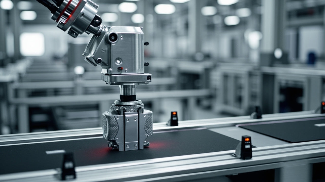
Essential Motion Control Commands: A Practical Guide for Engineers
Automation engineers often rely on precise position and speed control to drive modern factory machinery. Modern industrial systems, such as Programmable Logic Controllers (PLCs) and Distributed Control Systems (DCS), depend heavily on standardized motion instructions. Mastering these commands ensures operational safety, protects mechanical components, and optimizes cycle times across production lines.

The Role of Intrinsic Safety Barriers in PLC and DCS Architectures
Implementing robust protection in hazardous industrial environments represents a fundamental safety requirement in factory automation. Process facilities often handle volatile gases, dusts, and chemical agents that pose significant combustion risks. Consequently, control system engineers must deploy energy-limiting interfaces to isolate safe-area control cabinets from hazardous-area field instrumentation. This article examines the function, selection, and electrical principles of intrinsic safety barriers within modern PLC and DCS networks.