


Product Details
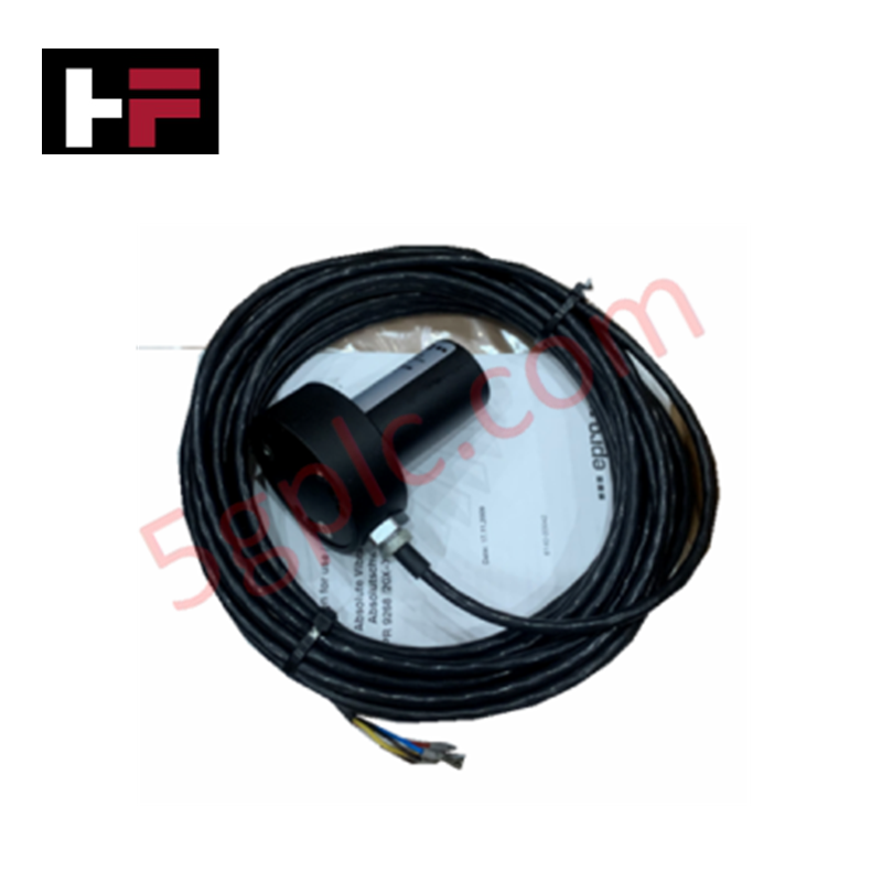
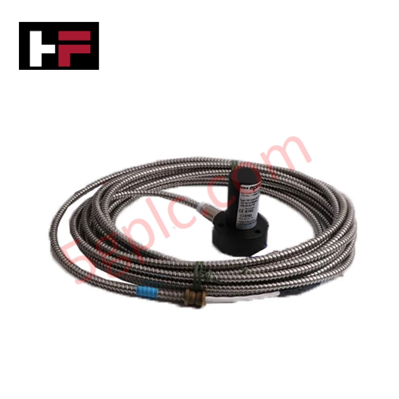
Configured for seismic vibration acquisition in rotating machinery, the Emerson EPRO PR9268/206-100 (PR9268/206-100) Electrodynamic Velocity Sensor provides direct electrical execution of velocity-based vibration monitoring.
Hardware Specifications
| Parameter | Specification |
|---|---|
| Model | PR9268/206-100 |
| Brand | Emerson EPRO |
| Weight | 280 g |
| Operating Temp | -20 deg C to +100 deg C |
| Power Consumption | Passive (no external power) |
| Sensitivity | 28.5 mV/mm/s (+/- 5%) |
| Frequency Range | 4 to 1000 Hz (+/- 3 dB) |
Process Control and DCS Connectivity
The PR9268/206-100 integrates with standard DCS and PLC platforms capable of processing low-impedance analog voltage signals. To maintain signal fidelity, channel-to-channel isolation must be strictly maintained within the signal conditioner input to prevent ground loop currents from introducing measurement drift. As an electrodynamic component, the sensor generates an analog voltage output proportional to velocity, necessitating correct impedance matching at the receiving module—typically optimized for 100 kOhm input impedance. Shielded cabling is required to maintain noise immunity in high-electromagnetic interference environments; the shield must be terminated at a single common instrument ground to minimize common-mode potential.
Frequently Asked Questions
Q: Does the sensor require an external power supply to function?
A: No. The PR9268/206-100 is a passive electrodynamic device that generates its own output signal based on seismic mechanical motion. It requires no excitation voltage but must be connected to a high-impedance input circuit.
Q: How does the ambient humidity influence sensor performance?
A: The sensor is rated for 0 to 100% non-condensing humidity. If deployed in environments prone to condensation or direct water impingement, ensure the cable entry point and connector interface are verified against the IP55 protection rating to prevent moisture-induced insulation breakdown.
Field Installation Guidelines
- Secure the sensor housing to a flat, machined surface on the bearing housing or machinery casing using a high-stiffness stud mount to ensure maximum vibration transfer.
- Verify that the mounting axis corresponds to the targeted vibration plane; misalignment will result in vector attenuation and phase errors in the output signal.
- Terminate signal leads at the signal conditioner input using shielded twisted-pair cabling; observe correct polarity to maintain proper signal phasing.
- Route signal lines through grounded metallic conduit, maintaining physical separation from high-current motor leads or AC power lines to prevent induced noise.
- Perform a commissioning test by manually verifying the baseline voltage output at standstill and observing the velocity signal during initial machine acceleration to confirm loop integrity.
Additional Information
- 100% Genuine Parts: All products are original and authentic, ensuring reliable industrial performance.
- 30-Day Refund Guarantee: Return any in-stock item within 30 days in original, unopened packaging for a full refund (excluding shipping and fees).
- 12-Month Warranty: Covers defects in materials or workmanship; excludes misuse, normal wear, or unauthorized modifications.
- Worldwide Shipping: We ship via USPS, UPS, FedEx, and DHL. Delivery times vary by country and may be subject to customs or import fees.
- Support & Contact: Technical and warranty assistance is available anytime. Contact us here: Contact.
- Purchase Guidance: Check product specifications and compatibility carefully before ordering to ensure proper application.


Tech & Buying Guide

Essential SCADA Features for Modern IoT-Enabled Industrial Automation
The convergence of traditional SCADA systems with the Industrial Internet of Things (IIoT) has redefined factory automation. Choosing a robust platform requires more than just standard monitoring capabilities. In this era of Industry 4.0, your supervisory system must bridge the gap between legacy control systems and enterprise-level data integration.

Selecting Rockwell Automation Allen-Bradley PLCs for Small and Mid-Sized Applications
Rockwell Automation remains a cornerstone in global industrial automation. Their Allen-Bradley brand provides a comprehensive portfolio of control systems designed to meet diverse production requirements. Choosing the right programmable logic controller (PLC) is critical for system reliability and scalability. This guide analyzes the Micro and Compact Logix families to help you select the optimal solution for small and medium-scale projects.

Strategic Selection: Choosing the Right SCADA Software for Your PLC Project
In industrial automation, the SCADA (Supervisory Control and Data Acquisition) system acts as the bridge between raw machine data and actionable human intelligence. Selecting the incorrect software platform can lead to integration bottlenecks, scalability issues, and excessive long-term maintenance costs. As an automation consultant with 15 years of experience, I have guided many projects through the selection process. Below are the essential criteria for choosing a platform that ensures both performance and longevity.