


Product Details
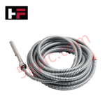
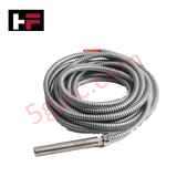
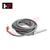
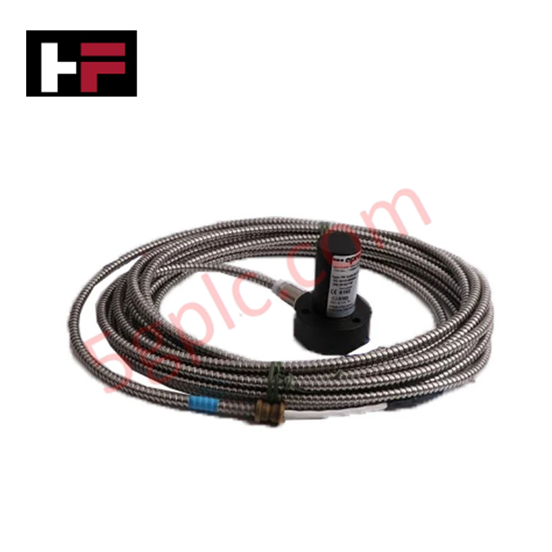
Configured for non-contact shaft displacement monitoring, the EPRO PR6426/010-140 (PR6426/010-140) Eddy Current Sensor+Eddy Current Signal Converter provides direct physical execution of proximity detection for rotating machinery.
Hardware Specifications
| Parameter | Specification |
|---|---|
| Model | PR6426/010-140 |
| Brand | EPRO |
| Operating Temp | -35 deg C to +120 deg C |
| Power Consumption | -18 to -26 VDC |
| Sensitivity | 8.0 mV/um (+/- 2%) |
| Frequency Response | 0 to 10000 Hz |
| Measurement Range | 0.5 to 2.5 mm |
Mechanical Monitoring and TSI Characteristics
The PR6426/010-140 functions via high-frequency electromagnetic field induction to determine the proximity of conductive surfaces. To ensure accurate measurement, the eddy-current probe scaling must be verified against the specific magnetic permeability of the target shaft material, such as AISI 4140 steel. During installation, gap voltage validation—targeting the midpoint of the linear operating range—is required to ensure the sensor response remains within its operational limits. In multi-channel TSI systems, cross-talk suppression must be enforced by maintaining minimum physical separation between adjacent probe tips to prevent frequency interference in the oscillator circuits.
Frequently Asked Questions
Q: Can the integral 3-conductor shielded cable be shortened or extended in the field?
A: The cable is a matched component of the inductive oscillator circuit. Modifying the cable length alters the circuit impedance and resonance frequency, which will induce significant measurement errors. Changes to cabling must only be executed using factory-approved matched extension cables.
Q: What are the consequences of mounting the probe in non-ferrous material?
A: Sensitivity is defined by the magnetic properties of the target. Non-ferrous materials exhibit different eddy-current damping characteristics, rendering the standard sensitivity of 8.0 mV/um invalid. Recalibration or application of a specific material correction factor is required for non-ferrous targets.
Field Installation Guidelines
- Mount the probe into a rigid bracket to prevent mechanical vibration of the probe body, which is indistinguishable from shaft displacement in the output signal.
- Verify the air gap using a calibrated feeler gauge to ensure the output voltage aligns with the nominal -10 VDC gap setting.
- Terminate the shield at the signal conditioner end to a common instrument ground; ensure the shield does not contact the machine casing to prevent ground loops.
- Separate signal cabling from high-power AC or VFD cables to minimize electromagnetic noise coupling into the high-frequency probe circuit.
- Perform a commissioning verify at operational speed to ensure the output signal does not drift due to thermal expansion of the machine housing.
Additional Information
- 100% Genuine Parts: All products are original and authentic, ensuring reliable industrial performance.
- 30-Day Refund Guarantee: Return any in-stock item within 30 days in original, unopened packaging for a full refund (excluding shipping and fees).
- 12-Month Warranty: Covers defects in materials or workmanship; excludes misuse, normal wear, or unauthorized modifications.
- Worldwide Shipping: We ship via USPS, UPS, FedEx, and DHL. Delivery times vary by country and may be subject to customs or import fees.
- Support & Contact: Technical and warranty assistance is available anytime. Contact us here: Contact.
- Purchase Guidance: Check product specifications and compatibility carefully before ordering to ensure proper application.


Tech & Buying Guide

Essential SCADA Features for Modern IoT-Enabled Industrial Automation
The convergence of traditional SCADA systems with the Industrial Internet of Things (IIoT) has redefined factory automation. Choosing a robust platform requires more than just standard monitoring capabilities. In this era of Industry 4.0, your supervisory system must bridge the gap between legacy control systems and enterprise-level data integration.

Selecting Rockwell Automation Allen-Bradley PLCs for Small and Mid-Sized Applications
Rockwell Automation remains a cornerstone in global industrial automation. Their Allen-Bradley brand provides a comprehensive portfolio of control systems designed to meet diverse production requirements. Choosing the right programmable logic controller (PLC) is critical for system reliability and scalability. This guide analyzes the Micro and Compact Logix families to help you select the optimal solution for small and medium-scale projects.

Strategic Selection: Choosing the Right SCADA Software for Your PLC Project
In industrial automation, the SCADA (Supervisory Control and Data Acquisition) system acts as the bridge between raw machine data and actionable human intelligence. Selecting the incorrect software platform can lead to integration bottlenecks, scalability issues, and excessive long-term maintenance costs. As an automation consultant with 15 years of experience, I have guided many projects through the selection process. Below are the essential criteria for choosing a platform that ensures both performance and longevity.