


Product Details
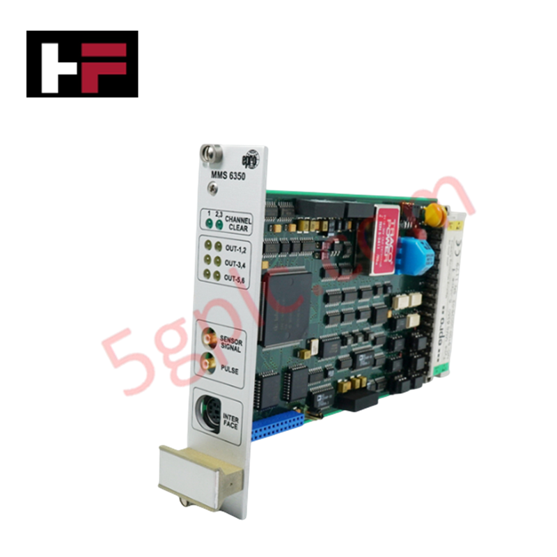
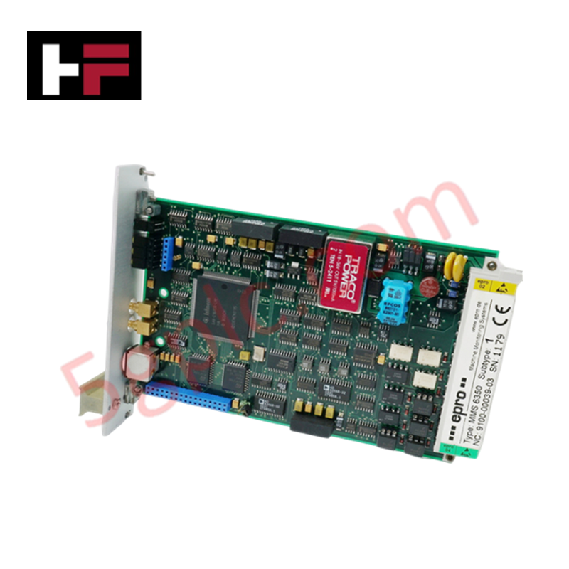
Configured for precision turbine speed monitoring and safety-critical protection, the Emerson EPRO MMS 6350/DP (MMS 6350/DP) Digital Overspeed Protection System provides direct physical execution of rotational speed acquisition and safety logic triggers.
Suffix Breakdown & Model Matrix
- MMS 6350: Base platform for digital overspeed protection.
- DP: Integrated PROFIBUS-DP communication interface for system-wide data integration.
Hardware Specifications
| Parameter | Specification |
|---|---|
| Model | MMS 6350/DP |
| Brand | Emerson EPRO |
| Origin | Not specified |
| Weight | 0.2 kg |
| Dimensions | 3.1 cm x 19 cm x 12.9 cm |
| Operating Temp | -40 deg C to +70 deg C |
| Accuracy | +/- 0.1 % |
| Resolution | 0.1 rpm |
High-Reliability Safety Control and SIS Characteristics
The MMS 6350/DP is certified to SIL3 standards per DIN EN 61508, ensuring high-integrity operation in safety-critical applications. The system employs fail-safe state execution to detect rotational velocity anomalies and initiate protection sequences. While it integrates PROFIBUS-DP for data transmission, the internal monitoring circuitry maintains galvanic isolation between the sensor input stage and the fieldbus communication path, protecting the system from electromagnetic transients. The architecture is designed to maintain functional safety in demanding environments, providing precise inputs for logic solvers that require validated speed data for turbine trip operations.
Frequently Asked Questions
Q: Can the MMS 6350/DP pulse outputs be used for direct actuator control?
A: The pulse outputs are limited to 48 VDC and 25 mA. They are designed for signal transmission to secondary logic devices; high-current loads must be driven through an intermediary interposing relay to prevent damage to the output stage.
Q: How does the system handle communication loss on the PROFIBUS-DP interface?
A: The system is designed for fail-safe state execution. Loss of communication with the master controller does not affect the local overspeed monitoring and protection logic, which remains operational based on the locally processed pulse frequency inputs.
Field Installation Guidelines
- Ensure the module is securely mounted in the designated rack, maintaining clearance for cooling and access to the PROFIBUS-DP port.
- Route the sensor input cabling away from high-voltage AC lines to prevent induced interference on the high-impedance (100 kOhm) input terminals.
- Verify that the cable shield for the PROFIBUS-DP segment is properly terminated at the system ground to maintain electrical isolation and signal integrity.
- Set the PROFIBUS station address correctly before power-up to ensure seamless integration with the host control network.
- Perform a functional check by simulating frequency pulses at the input terminals and verifying that the TTL and pulse outputs respond according to the defined trip setpoints.
Additional Information
- 100% Genuine Parts: All products are original and authentic, ensuring reliable industrial performance.
- 30-Day Refund Guarantee: Return any in-stock item within 30 days in original, unopened packaging for a full refund (excluding shipping and fees).
- 12-Month Warranty: Covers defects in materials or workmanship; excludes misuse, normal wear, or unauthorized modifications.
- Worldwide Shipping: We ship via USPS, UPS, FedEx, and DHL. Delivery times vary by country and may be subject to customs or import fees.
- Support & Contact: Technical and warranty assistance is available anytime. Contact us here: Contact.
- Purchase Guidance: Check product specifications and compatibility carefully before ordering to ensure proper application.


Tech & Buying Guide

Essential SCADA Features for Modern IoT-Enabled Industrial Automation
The convergence of traditional SCADA systems with the Industrial Internet of Things (IIoT) has redefined factory automation. Choosing a robust platform requires more than just standard monitoring capabilities. In this era of Industry 4.0, your supervisory system must bridge the gap between legacy control systems and enterprise-level data integration.

Selecting Rockwell Automation Allen-Bradley PLCs for Small and Mid-Sized Applications
Rockwell Automation remains a cornerstone in global industrial automation. Their Allen-Bradley brand provides a comprehensive portfolio of control systems designed to meet diverse production requirements. Choosing the right programmable logic controller (PLC) is critical for system reliability and scalability. This guide analyzes the Micro and Compact Logix families to help you select the optimal solution for small and medium-scale projects.

Strategic Selection: Choosing the Right SCADA Software for Your PLC Project
In industrial automation, the SCADA (Supervisory Control and Data Acquisition) system acts as the bridge between raw machine data and actionable human intelligence. Selecting the incorrect software platform can lead to integration bottlenecks, scalability issues, and excessive long-term maintenance costs. As an automation consultant with 15 years of experience, I have guided many projects through the selection process. Below are the essential criteria for choosing a platform that ensures both performance and longevity.