










Product Details
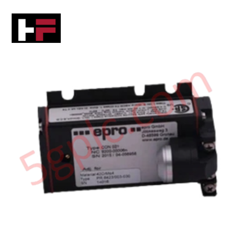
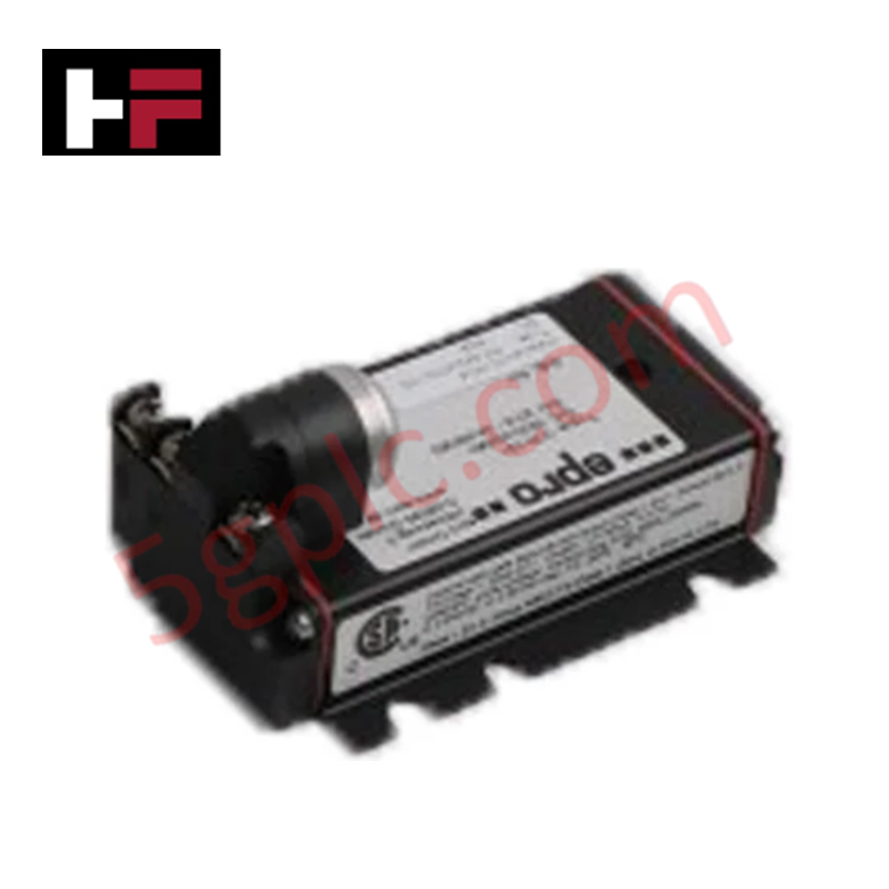
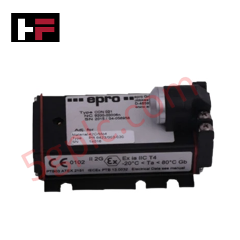
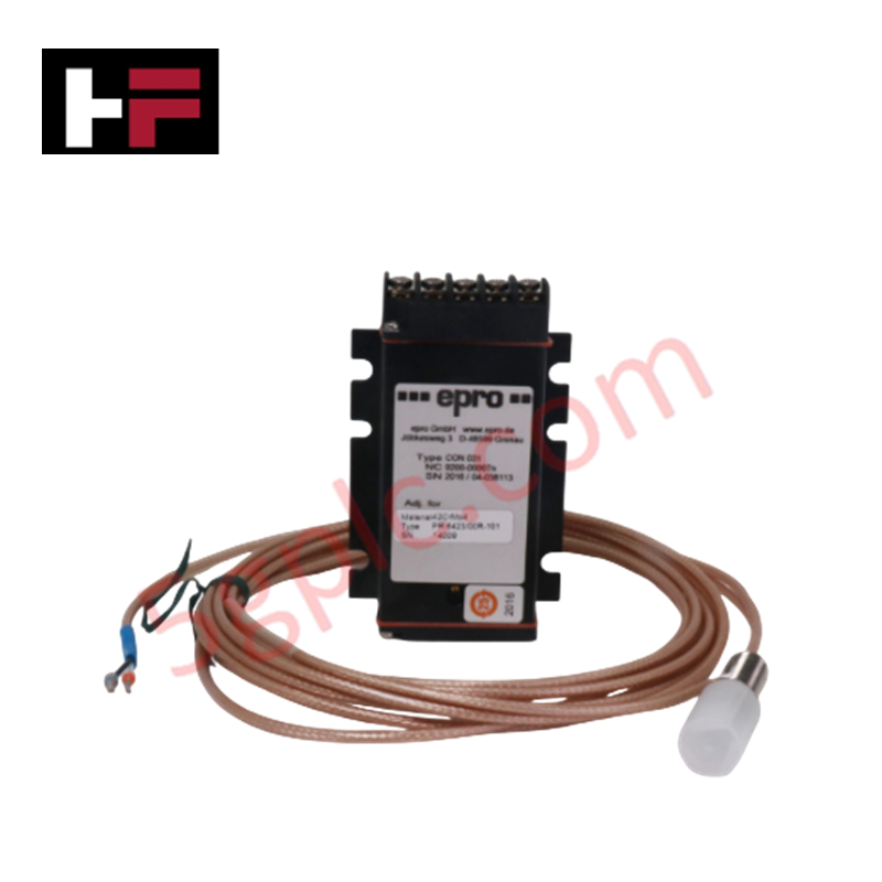
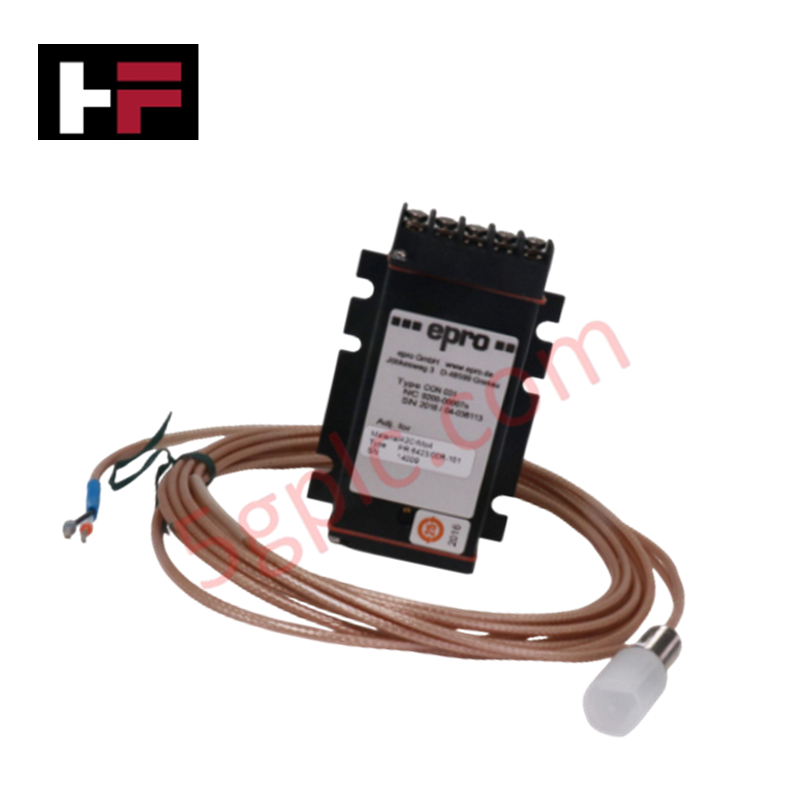
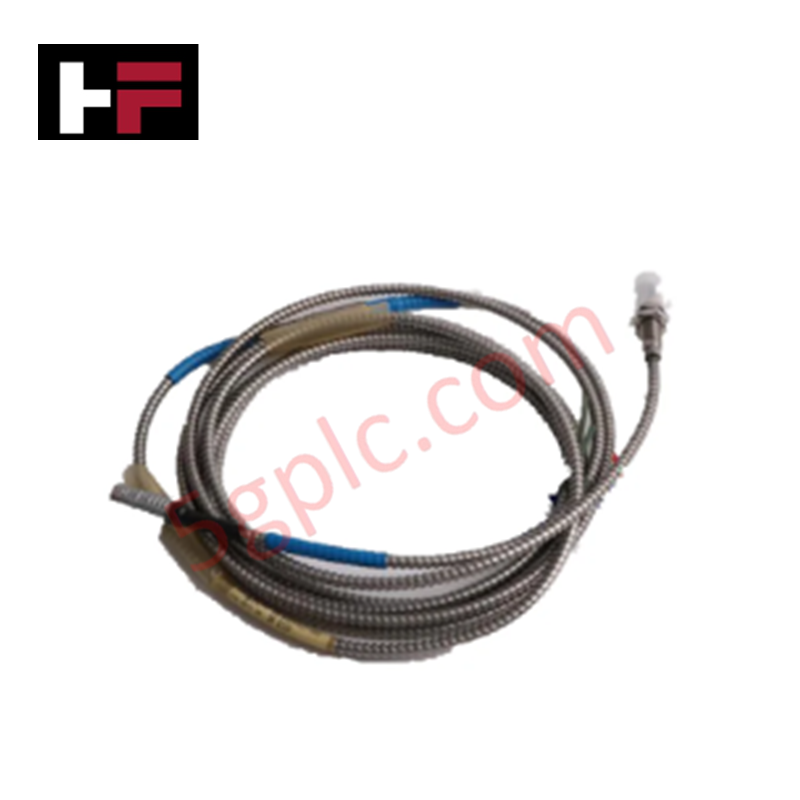
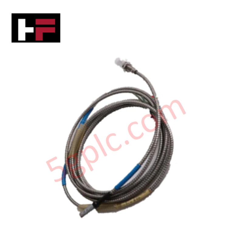
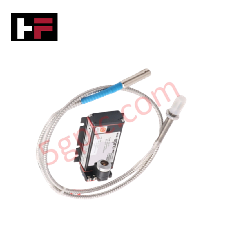
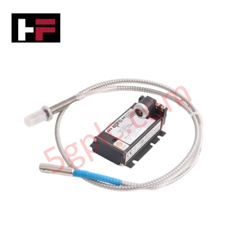
Configured for high-frequency vibration signal conditioning in turbomachinery monitoring systems, the EPRO CON021/916-160 (CON021/916-160) Eddy Current Signal Converter provides direct physical/electrical execution.
Hardware Specifications
| Parameter | Specification |
|---|---|
| Model | CON021/916-160 |
| Brand | EPRO |
| Origin | Germany |
| Weight | 0.8 kg |
| Dimensions | 16 cm x 16 cm x 12 cm |
| Operating Temp | Industrial grade specification |
| Power Consumption | Nominal loop-powered |
| Catalog | PR6426 |
Gap Voltage Validation (-10 VDC targets)
The CON021/916-160 converter utilizes an oscillator circuit to drive the eddy current transducer probe. To ensure a linear response, the system requires precise gap voltage validation. The operating range is typically centered on a target of -10 VDC, which corresponds to the median measurement gap between the sensor face and the conductive target. Any deviation from this nominal gap voltage during static conditions indicates potential installation misalignment or transducer degradation, which directly affects the converter's ability to linearize the output signal.
Frequently Asked Questions
Q: Is the CON021/916-160 compatible with other EPRO probe models?
A: The converter is calibrated as part of a matched system (PR6426 series). Use with non-specified transducers will result in measurement non-linearity and loss of accuracy.
Q: Does this converter support field adjustment of the output offset?
A: Internal calibration settings are factory-set. Field adjustments are limited to mechanical gap positioning to achieve the nominal -10 VDC center-gap voltage.
Field Installation Guidelines
- Mount the converter within an IP20-compliant enclosure to protect the internal circuitry from moisture and conductive dust.
- Ensure the transducer probe is installed in a rigid bracket, maintaining at least 15 mm of clearance from other metallic objects to avoid cross-talk.
- Verify that the cable connections are secure; the Lemo-plug or screw terminals must be tightened to prevent intermittent signal noise.
- Ground the signal cable shield at the monitoring system (DCS/TSI) rack only to eliminate ground loops.
- Confirm the power supply polarity is correct before energizing the loop to prevent internal electronic fault.
Additional Information
- 100% Genuine Parts: All products are original and authentic, ensuring reliable industrial performance.
- 30-Day Refund Guarantee: Return any in-stock item within 30 days in original, unopened packaging for a full refund (excluding shipping and fees).
- 12-Month Warranty: Covers defects in materials or workmanship; excludes misuse, normal wear, or unauthorized modifications.
- Worldwide Shipping: We ship via USPS, UPS, FedEx, and DHL. Delivery times vary by country and may be subject to customs or import fees.
- Support & Contact: Technical and warranty assistance is available anytime. Contact us here: Contact.
- Purchase Guidance: Check product specifications and compatibility carefully before ordering to ensure proper application.




Tech & Buying Guide

Top 5 Operational Advantages of HMIs in Modern Factory Automation

Importance of Safety Barriers in PLC and DCS Control Systems
