










Product Details
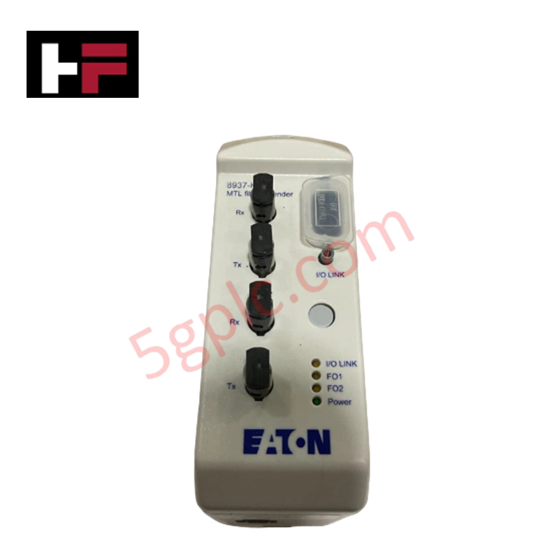
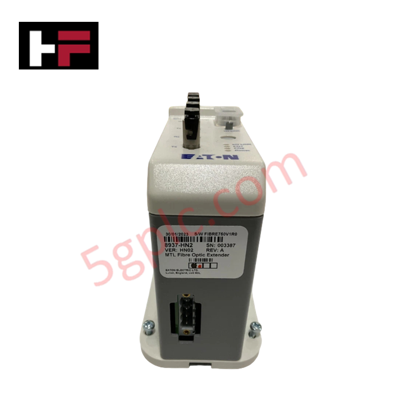
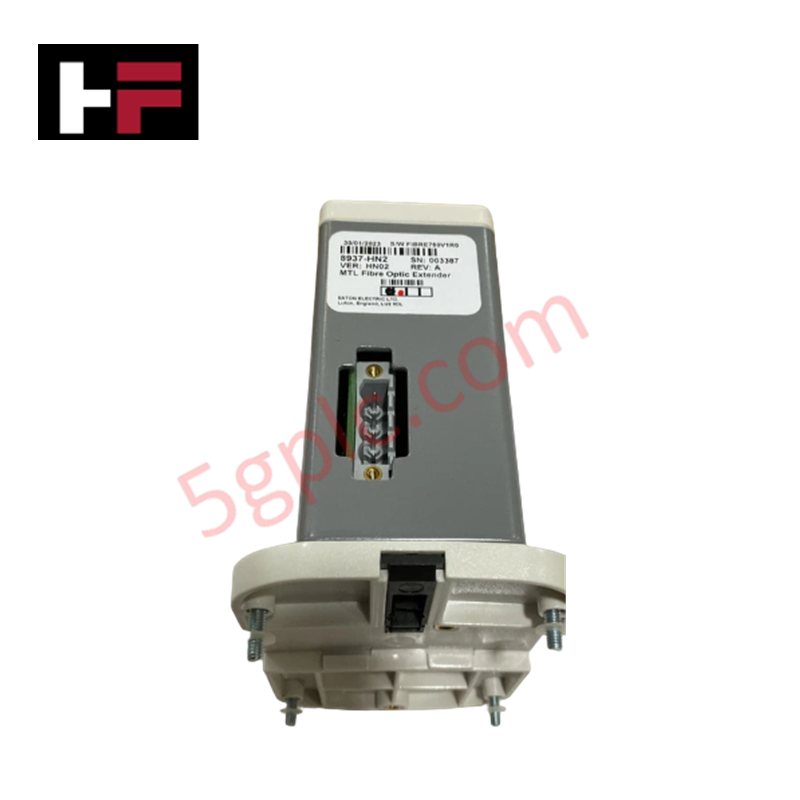
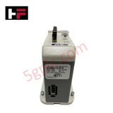
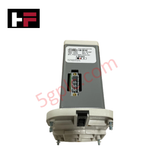
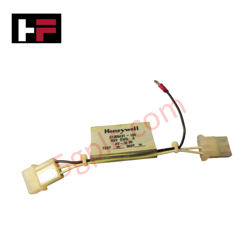
The Honeywell 8937-HN2, also cataloged as the 8937-HN2 Fiber Optic Extender Module, operates as a dedicated hardware component for extending I/O link signal transmission over optical fiber networks within Honeywell industrial control platforms.
Hardware Specifications
| Parameter | Specification |
|---|---|
| Model | 8937-HN2 |
| Brand | Honeywell |
| Origin | USA / As specified on hardware label |
| Weight | 500 g (1.10 lbs) |
| Dimensions | 150 mm x 100 mm x 50 mm |
| Operating Temp | -40 to 85 deg C |
| Power Consumption | 12-36 VDC input voltage range |
| Module Type | Fiber Optic Extender Module |
| Output Voltage Range | 0-10 VDC |
| Maximum Output Current | 5 A |
| Protection Rating | IP67 |
FOUNDATION Fieldbus and Channel-to-Channel Isolation
The 8937-HN2 optical transceiver conversion circuitry drives serial data streams over optical link topologies to bypass copper distance limitations. Integrated signal conditioning provides channel-to-channel isolation across internal power and communication pathways, preventing ground loop circulation and electromagnetic interference from corrupting critical field data. This optical isolation framework ensures deterministic telemetry routing for connected remote devices, supporting 4-20 mA HART loop protocol interfaces and FOUNDATION Fieldbus segments extended across distributed control networks.
Frequently Asked Questions
Q: What is the operating voltage range supported by the 8937-HN2 power terminal block?
A: The module accepts a wide direct current input range from 12 VDC to 36 VDC.
Q: How does optical conversion protect control system signals in high-noise environments?
A: Converting copper signal links to optical fiber provides total galvanic isolation, eliminating common-mode noise, ground potential differences, and inductive surge interference across long transmission paths.
Field Installation Guidelines
- Mount the 8937-HN2 enclosure securely using the integral mounting points, ensuring the IP67 seal integrity is maintained if exposed to harsh ambient conditions.
- Inspect all optical fiber connectors for cleanliness and dust contamination before inserting them into the transceiver ports.
- Connect incoming 12-36 VDC power leads to the designated screw terminals, verifying correct polarity prior to energizing the module.
- Ensure all metallic cable glands and shield drain wires are tied to a dedicated local earth ground point to maintain noise suppression standards.
Additional Information
- 100% Genuine Parts: All products are original and authentic, ensuring reliable industrial performance.
- 30-Day Refund Guarantee: Return any in-stock item within 30 days in original, unopened packaging for a full refund (excluding shipping and fees).
- 12-Month Warranty: Covers defects in materials or workmanship; excludes misuse, normal wear, or unauthorized modifications.
- Worldwide Shipping: We ship via USPS, UPS, FedEx, and DHL. Delivery times vary by country and may be subject to customs or import fees.
- Support & Contact: Technical and warranty assistance is available anytime. Contact us here: Contact.
- Purchase Guidance: Check product specifications and compatibility carefully before ordering to ensure proper application.


Tech & Buying Guide
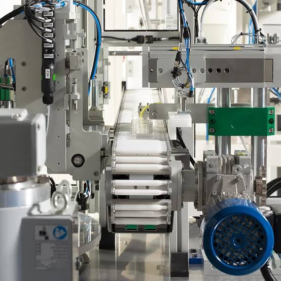
Mastering Modern Industrial Joystick Controls in Heavy Automation
Industrial joysticks play a pivotal role in human-machine interaction across heavy material handling and mobile hydraulics. These tactile controllers translate complex operator movements into precise electrical signals for PLCs, motion controllers, and DCS networks. Consequently, selecting and installing the right joystick architecture ensures operator safety, reduces fatigue, and optimizes equipment performance.

Navigating Industrial Automation Failures: Types, Causes, and Mitigation Strategies
Modern manufacturing relies heavily on automated control systems to maximize throughput and maintain product quality. However, unplanned downtime in industrial automation can cost facility operators thousands of dollars per hour. Understanding how programmable logic controllers (PLCs), distributed control systems (DCS), and field instrumentation fail empowers engineering teams to implement robust preventive maintenance strategies.
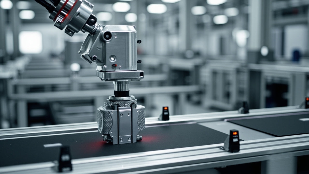
Essential Motion Control Commands: A Practical Guide for Engineers
Automation engineers often rely on precise position and speed control to drive modern factory machinery. Modern industrial systems, such as Programmable Logic Controllers (PLCs) and Distributed Control Systems (DCS), depend heavily on standardized motion instructions. Mastering these commands ensures operational safety, protects mechanical components, and optimizes cycle times across production lines.