










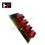
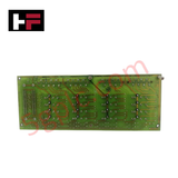
Product Details
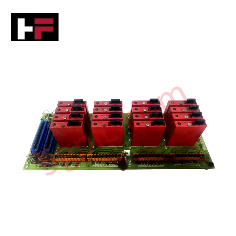
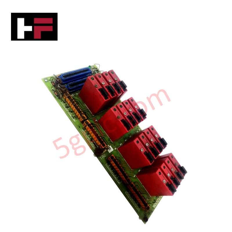
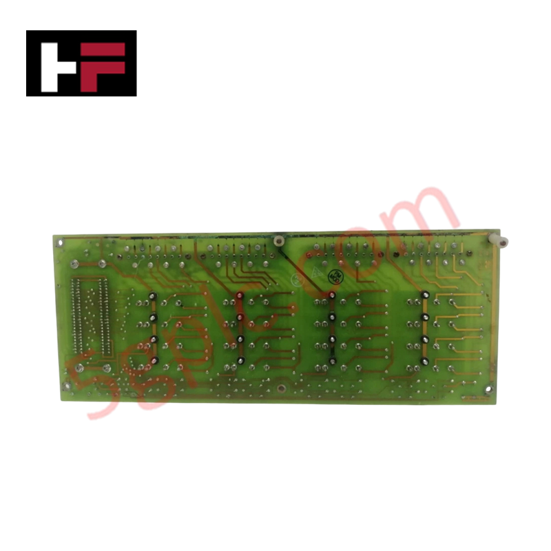
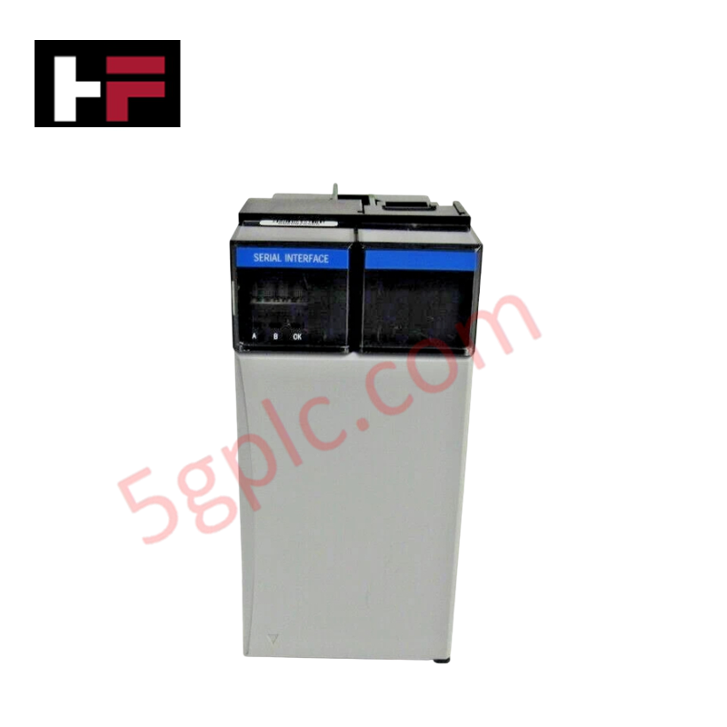
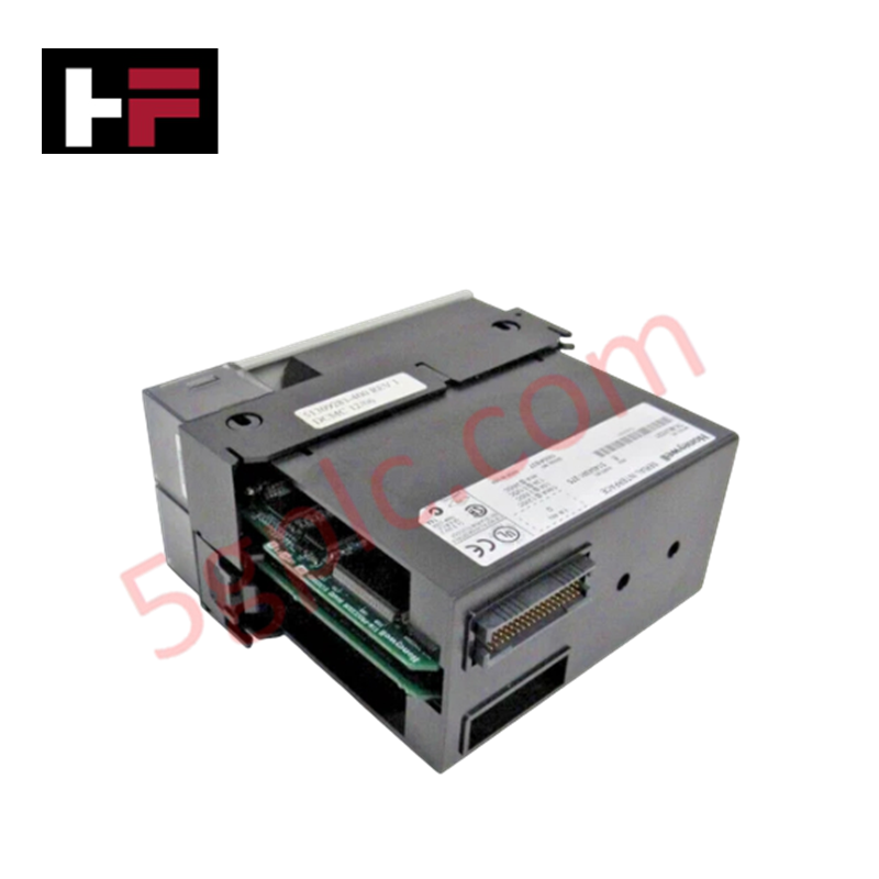
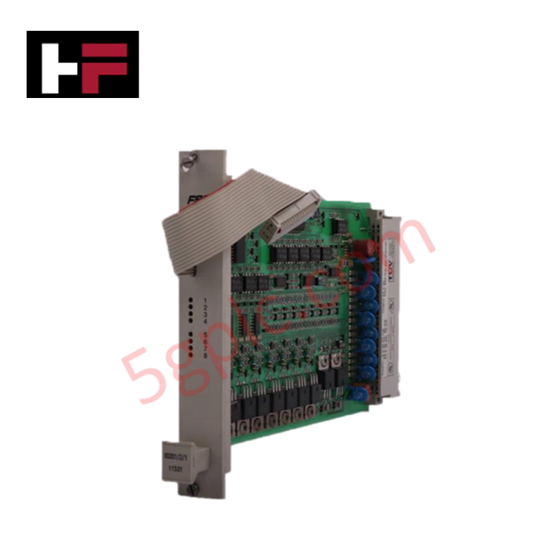
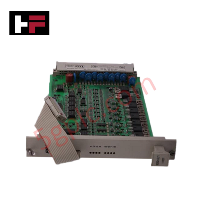
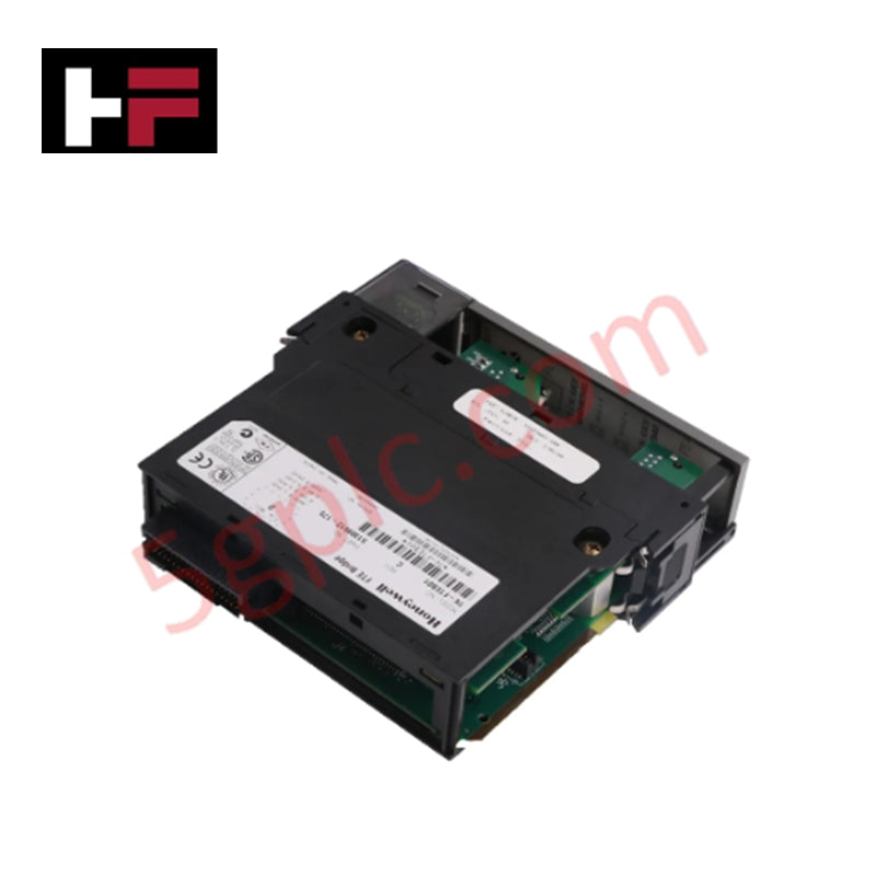
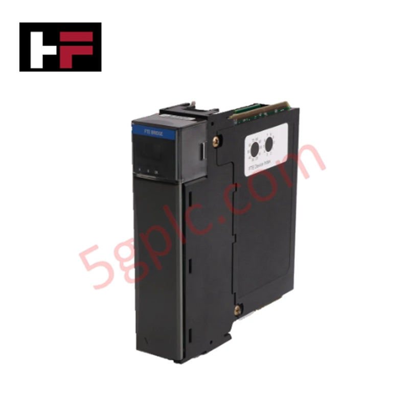
Configured for high-density digital signal switching in Universal Control Network platforms, the Honeywell 51304650-100 (MU-TD0D13 Field Termination Assembly) provides direct physical/electrical execution. The hardware assembly acts as the physical link between the control network processor and discrete field elements, executing switching sequences for load devices across integrated optical barriers without deploying mechanical contacts.
Hardware Specifications
| Parameter | Specification |
|---|---|
| Model | 51304650-100 (MU-TD0D13) |
| Brand | Honeywell |
| Series / Module Type | UCN / Digital Output Field Termination Assembly |
| Origin | USA |
| Weight | 1.02 kg |
| Dimensions | 30.7 cm x 12 cm x 8 cm |
| Operating Temp | -40 to +70 deg C |
| Power Consumption | Base backplane loop drawn, 0.5 A max per channel output |
| Output Channels | 16 optically isolated outputs |
| Output Voltage Range | 3-30 VDC |
| Isolation Rating | 500 VAC |
| Fuse Rating | 2.5 A |
| Terminal Type | Compression terminals |
| Hazardous Location Rating | Class I, Division 2, Groups A, B, C, D |
Channel-to-Channel Isolation and Digital Signal Control
The Honeywell 51304650-100 features a 16-channel architecture embedded with 500 VAC optical isolation barriers to establish distinct channel-to-channel isolation. This configuration interrupts electrical noise paths and dampens ground loops between the field field devices and the internal control logic. Supporting a 3-30 VDC voltage range at 0.5 A per channel, the solid-state switching matrices execute commands with minimal latency. Circuit protection is maintained via a 2.5 A fuse block, ensuring electrical faults on a single current loop remain isolated from adjacent channels.
Frequently Asked Questions
Q: How does the module handle a sustained overcurrent event on an individual output channel?
A: Each circuit grouping relies on the integrated 2.5 A fuse matrix. If a field device fault causes the current to exceed the breakdown threshold, the fuse opens to interrupt the circuit path, providing physical loop isolation to protect the solid-state switching components from thermal overload.
Q: Can this Field Termination Assembly be hot-swapped while the Universal Control Network is active?
A: Module removal or terminal disconnects must only be performed when the field power loop is de-energized or when the environment is verified to be non-hazardous. Live handling in Class I, Division 2 locations risks initiating spark discharges across the compression terminal points.
Field Installation Guidelines
- Orientation and Mounting: Secure the assembly plate to the cabinet columns using the integrated chassis mounting points. Maintain a minimum clear boundary of 5 cm around the ventilation paths to ensure thermal dissipation across the -40 to +70 deg C temperature limits.
- Compression Terminal Connections: Insert the field wire conductors into the dedicated compression terminals. Tighten the clamping screws to the manufacturer-specified torque limits to prevent intermittent open circuits under mechanical vibration.
- Shielding Protocols: Run discrete field cables via distinct low-voltage pathways separate from high-power distribution lines. Terminate all instrument shields at a single ground bus point within the marshaling enclosure to maximize channel-to-channel isolation.
- Hazardous Location Verification: Before energizing the 3-30 VDC external supply loop, verify that all terminal seals match the requirements for Class I, Division 2 installations to prevent electrical arc exposure.
Additional Information
- 100% Genuine Parts: All products are original and authentic, ensuring reliable industrial performance.
- 30-Day Refund Guarantee: Return any in-stock item within 30 days in original, unopened packaging for a full refund (excluding shipping and fees).
- 12-Month Warranty: Covers defects in materials or workmanship; excludes misuse, normal wear, or unauthorized modifications.
- Worldwide Shipping: We ship via USPS, UPS, FedEx, and DHL. Delivery times vary by country and may be subject to customs or import fees.
- Support & Contact: Technical and warranty assistance is available anytime. Contact us here: Contact.
- Purchase Guidance: Check product specifications and compatibility carefully before ordering to ensure proper application.


Tech & Buying Guide

Understanding Safety Relays in Industrial Automation: Architecture, Operation, and Functional Safety
Standard electromechanical relays provide basic electrical isolation between low-voltage control circuits and high-power output loads. A traditional switching relay features a magnetic coil driving mechanical Common (COM), Normally-Open (NO), and Normally-Closed (NC) contacts. However, standard relays pose severe functional risks when deployed in critical safety interlock circuits. High current inrush or mechanical wear can weld contacts together permanently. If contact welding occurs in an emergency stop circuit, pressing the button fails to halt hazardous machinery movements. Consequently, global functional safety standards prohibit standard relays for critical machine guarding functions.

Mastering Wire Identification in Industrial Automation: The Power of Ferrules and Cross-Ferruling
Proper wire labeling forms the cornerstone of reliable control system installation and long-term maintenance. In complex industrial automation environments, technicians terminate thousands of conductor ends inside control panels, marshalling racks, and field junction boxes. Ferrules serve as individual tube-shaped sleeve markers slipped onto conductors before final termination. While technicians historically relied on pre-printed individual letter rings, modern control panel builders utilize automated ferrule printing machines. These thermal-transfer printers generate durable, single-sleeve heat-shrink tags directly matching approved wiring schematics, significantly accelerating cabinet assembly workflows.

Understanding Marshalling Cabinets in Industrial Automation and Control Systems
Marshalling cabinets serve as the crucial connection hub between field instruments and centralized processing units. In large DCS and PLC control system architectures, hundreds of multipair field cables run from local junction boxes to the central instrument equipment room. The marshalling cabinet houses field terminal blocks, surge arresters, intrinsic safety isolation barriers, and interposing relays. By segregating field field-wiring terminations from sensitive processor hardware, engineers protect expensive controller backplanes from high-voltage transients. Consequently, this modular separation dramatically streamlines maintenance workflows and simplifies system expansion.