










Product Details
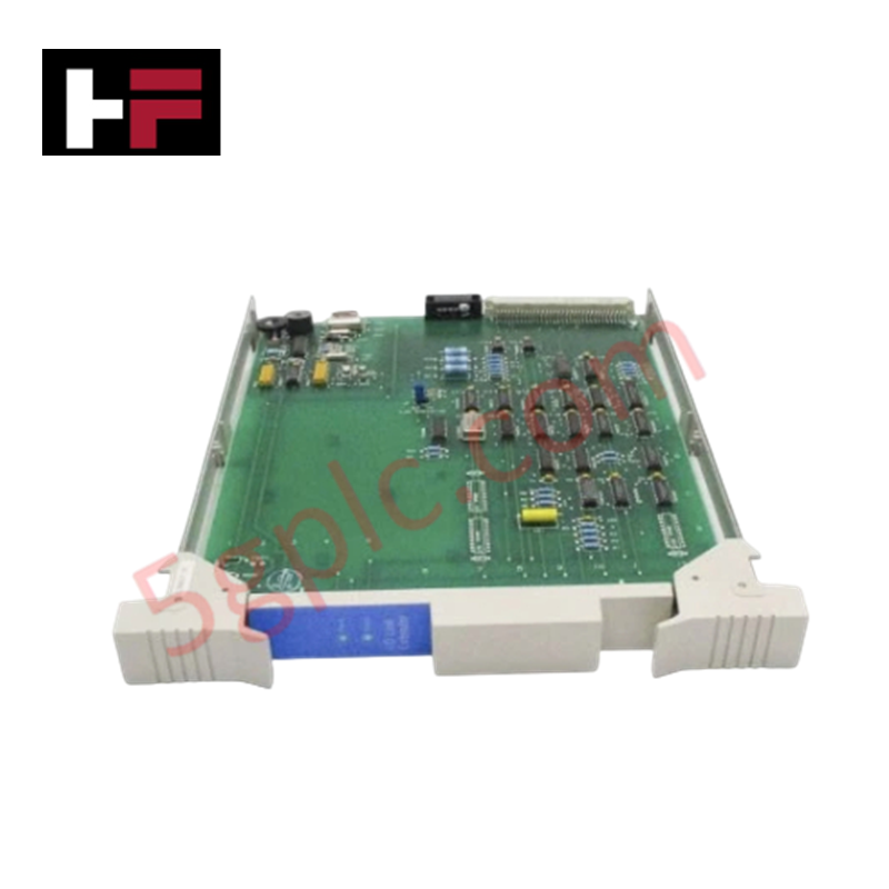
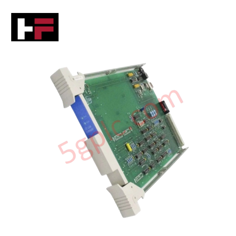
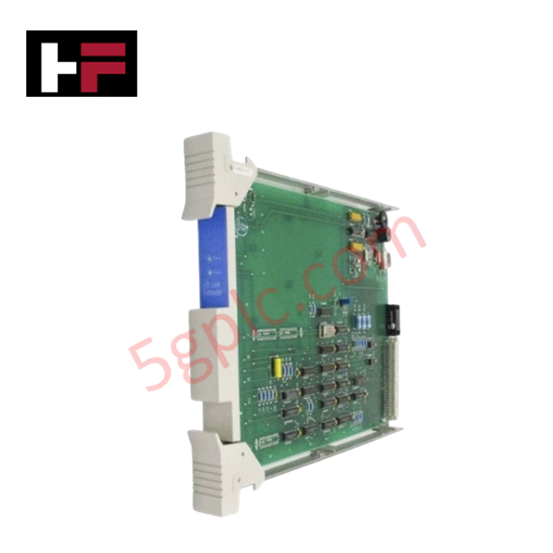
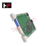
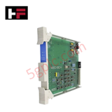
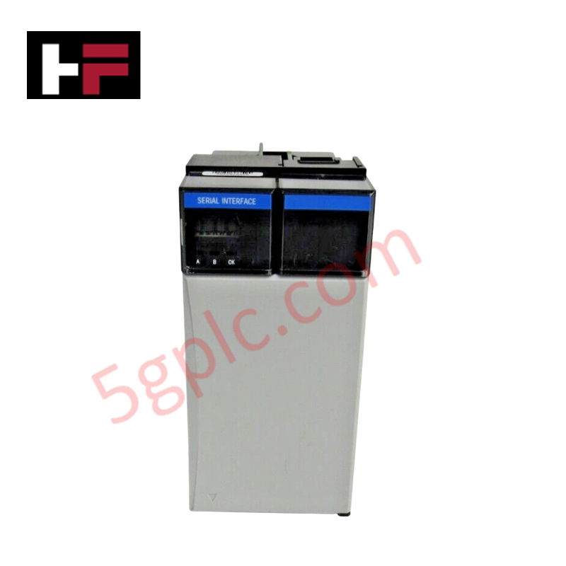
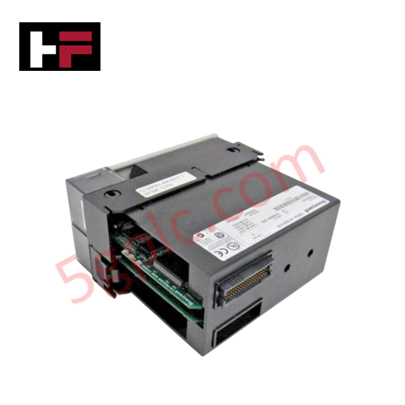
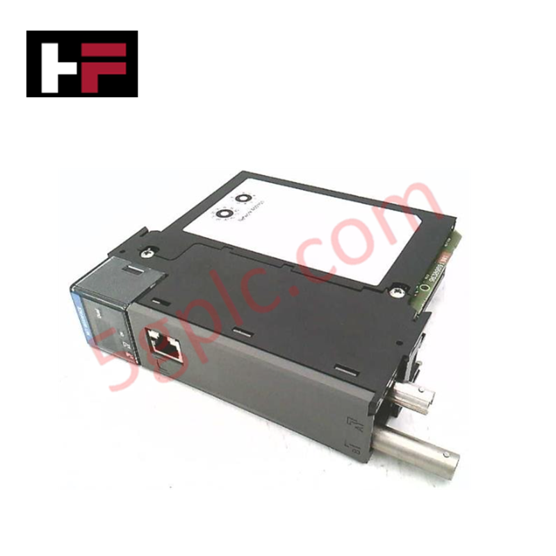
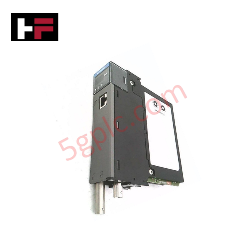
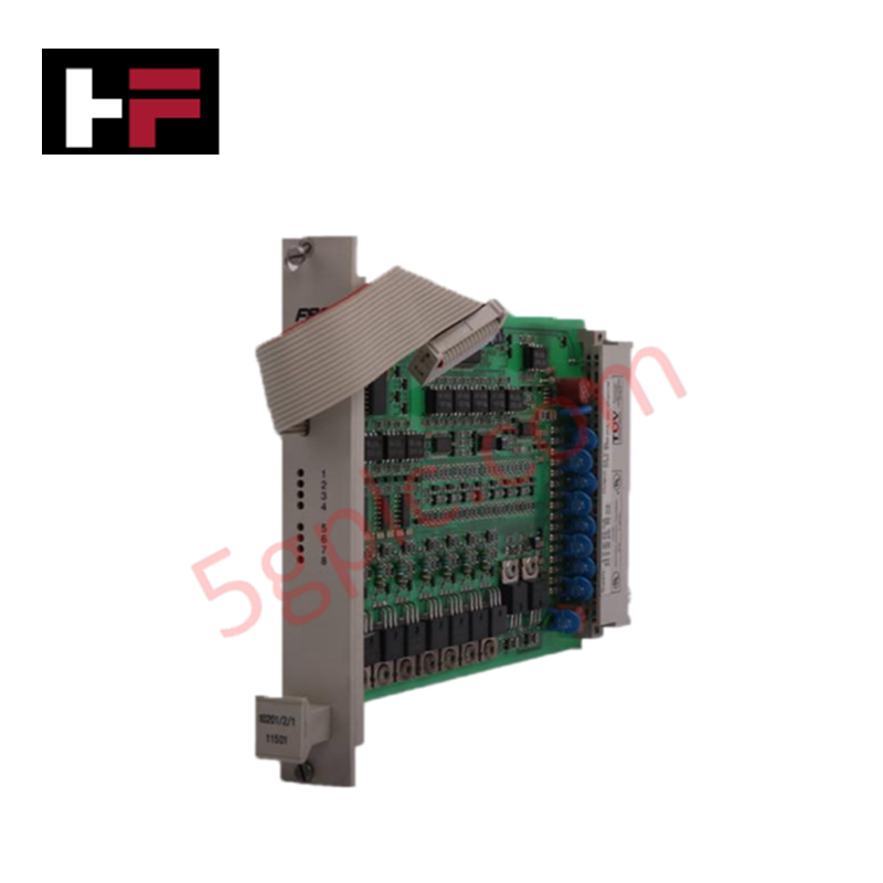
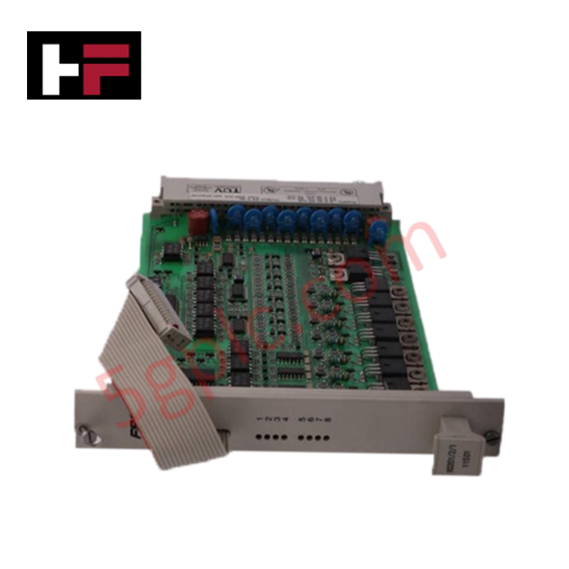
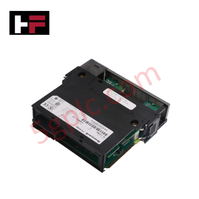
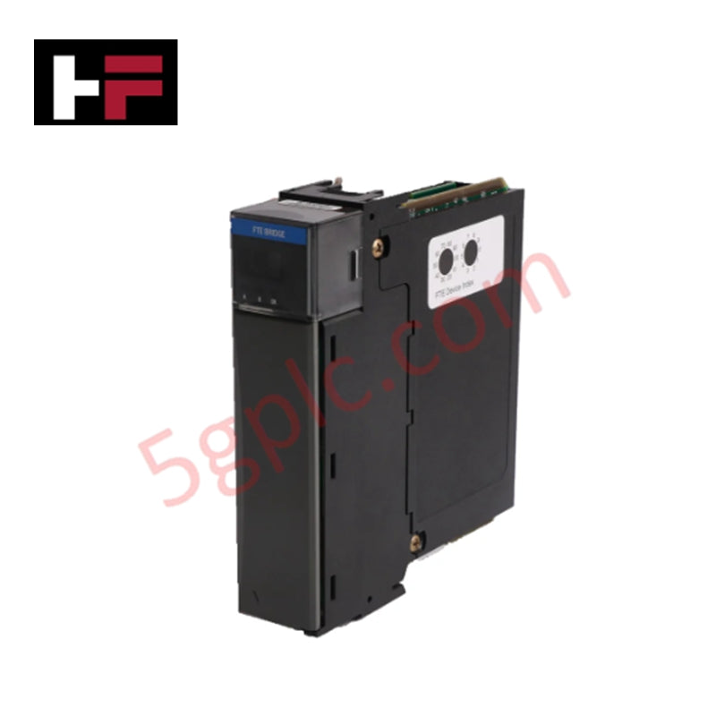
The Honeywell 51304419-100, also cataloged as the 51304419-100 I/O Link Extender, operates as a dedicated hardware component for extending PM/APM/HPM I/O link interface signals across fiber optic links within Honeywell DCS networks.
Hardware Specifications
| Parameter | Specification |
|---|---|
| Model | 51304419-100 |
| Brand | Honeywell |
| Origin | USA |
| Weight | Approx. 6.00 kg (shipping weight) |
| Dimensions | Standard Honeywell IPC chassis module dimensions |
| Operating Temp | 0 deg C to +60 deg C |
| Power Consumption | Max. 10 W at system backplane supply rails |
| Function | Optical extension of PM, APM, and HPM I/O link buses |
| Optical Transmission Distance | 1.3 km or 8 km (depending on transceiver module) |
| Channel Redundancy | Dual-channel support (Link A and Link B) |
| Onboard Termination Control | Jumper J2 (LINK TERMINATION: IN / OUT) |
| Remote Bus Termination | Integrated jumper-selectable internal terminators |
4-20 mA HART Loop Protocol and Channel-to-Channel Isolation
The module converts electrical I/O link bus signals into optical pulses to enable long-distance signal transmission while establishing total optical channel-to-channel isolation between remote enclosures. By converting metallic bus lines to noise-immune fiber optics, the unit eliminates ground potential loops and high-frequency noise pickup, preserving continuous digital telemetry integrity for remote I/O subsystems executing 4-20 mA HART loop protocol passes.
Frequently Asked Questions
Q: How must the bus termination jumper J2 be configured on the 51304419-100 card?
A: Jumper J2 controls local link termination; both Link A and Link B must have termination enabled (IN) when positioned at physical cable segment endpoints, or disabled (OUT) when pass-through topology is required.
Q: What is the maximum fiber optic distance supported by the I/O Link Extender?
A: Transmission distance ranges up to 1.3 km or 8 km depending on the specific optical transceiver assembly and fiber optic cable specifications installed in the link.
Q: Are both Link A and Link B redundant channels supported on a single module?
A: Yes, the 51304419-100 processes both Link A and Link B channels simultaneously to maintain redundant controller-to-I/O link communication across separate enclosure cabinets.
Field Installation Guidelines
- De-energize system backplane power before seating or unseating the extender card within the chassis slot.
- Inspect and clean all fiber optic connector ferrule faces prior to insertion to prevent signal attenuation over long distance links.
- Set jumper J2 to IN on both physical ends of Link A and Link B to ensure proper electrical termination of the copper segments interfacing the optical transceiver.
- Ensure minimum fiber optic cable bend radius limits are observed during wire routing inside cabinet ducting to prevent signal degradation.
Additional Information
- 100% Genuine Parts: All products are original and authentic, ensuring reliable industrial performance.
- 30-Day Refund Guarantee: Return any in-stock item within 30 days in original, unopened packaging for a full refund (excluding shipping and fees).
- 12-Month Warranty: Covers defects in materials or workmanship; excludes misuse, normal wear, or unauthorized modifications.
- Worldwide Shipping: We ship via USPS, UPS, FedEx, and DHL. Delivery times vary by country and may be subject to customs or import fees.
- Support & Contact: Technical and warranty assistance is available anytime. Contact us here: Contact.
- Purchase Guidance: Check product specifications and compatibility carefully before ordering to ensure proper application.


Tech & Buying Guide

Essential Best Practices for PLC Wiring and Installation in Industrial Automation
Successful control system deployment begins with thoroughly reviewing manufacturer technical documentation. Controllers from major brands like Allen-Bradley, Siemens, and Schneider Electric feature unique terminal layouts. Engineers must verify voltage requirements before connecting power cables to prevent catastrophic equipment damage. Standard line connections require strict adherence to regional electrical codes and proper wire color coding. Furthermore, panel builders should always establish a robust low-impedance ground connection using at least 16-AWG copper conductor tied directly to the main plant grounding grid.
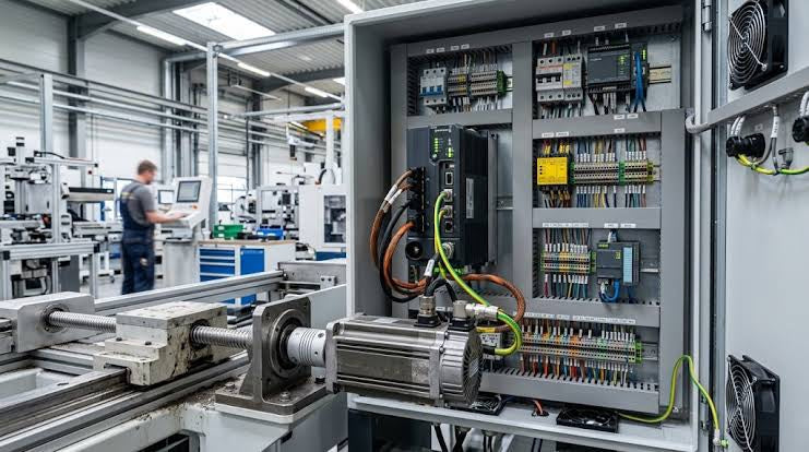
Demystifying Programmable Logic Controllers: Comprehensive Guide to PLC Classification and Selection in Industrial Automation
Modern industrial automation heavily relies on Programmable Logic Controllers (PLCs) to drive factory floor efficiency. Over my 15 years as an industrial automation expert working with DCS, TSI, and control systems, I have seen PLCs evolve into the central nervous system of modern manufacturing. Selecting the right controller requires a deep understanding of PLC types based on physical size, hardware architecture, and power supply configurations.

Comprehensive Guide to PLC Types in Modern Industrial Automation
Modern industrial automation relies on programmable logic controllers to govern critical factory operations. System integrators classify PLCs based on scale, hardware architecture, and power supply design. Understanding these core categories enables automation engineers to select the right control system architecture. Consequently, proper hardware selection optimizes performance while minimizing long-term operational costs.