










Product Details
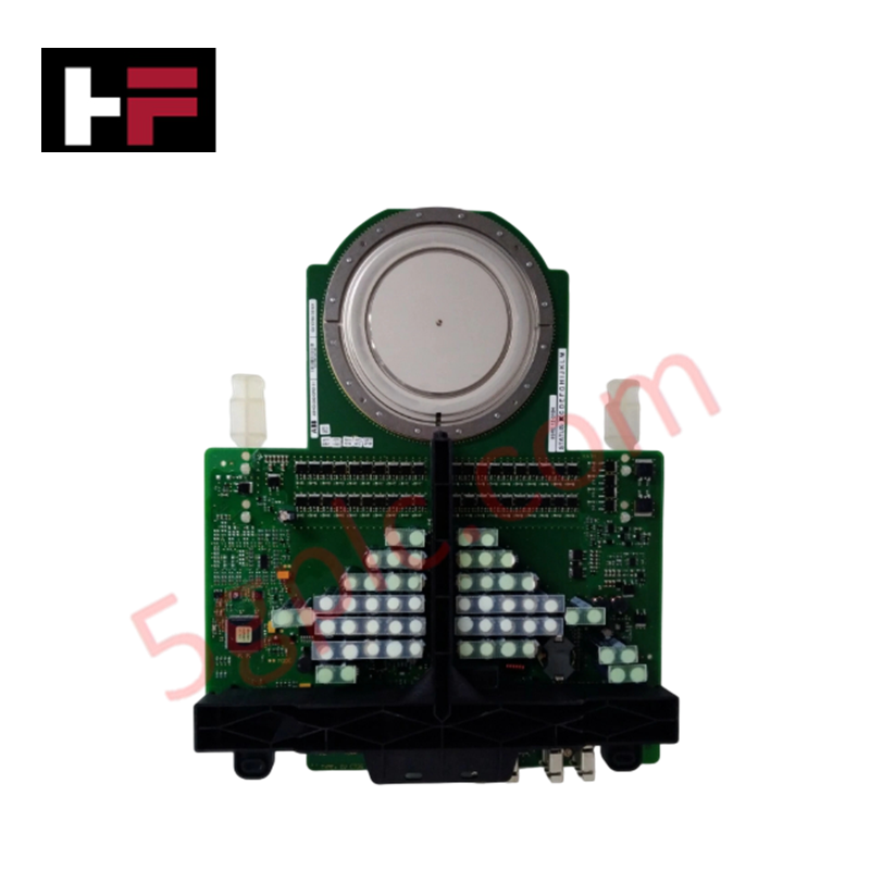
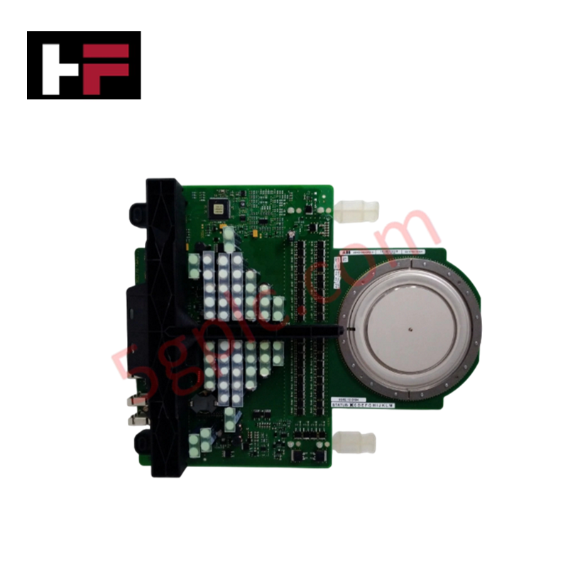
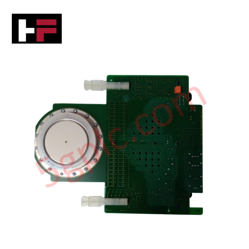
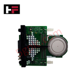
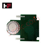
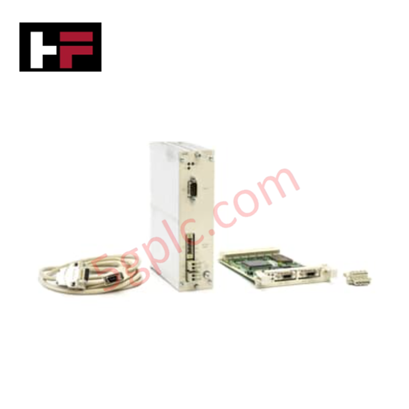
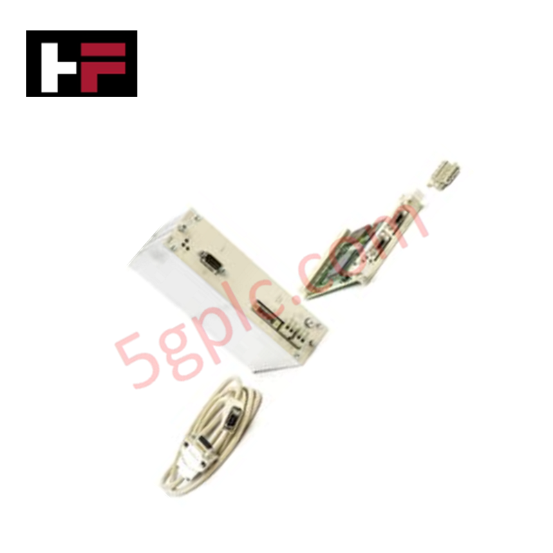
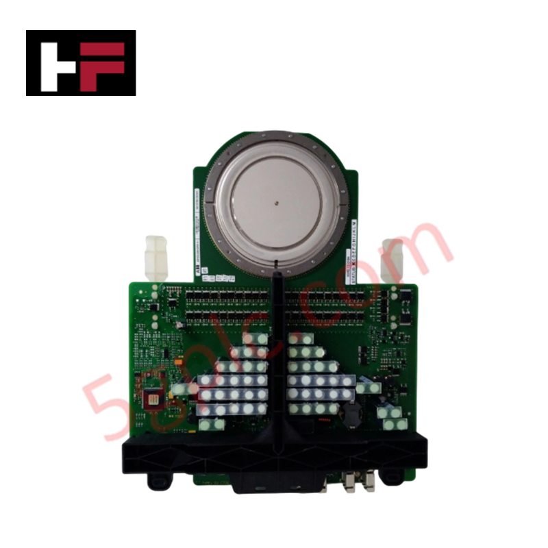
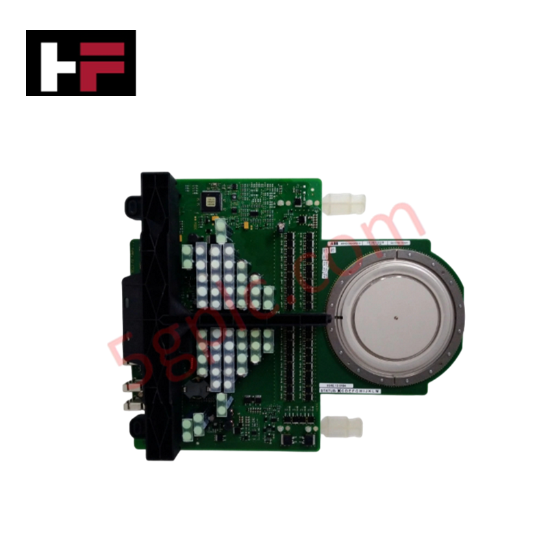
The ABB 5SHY3545L0020 3BHE014105R0001, also cataloged as the 5SHY3545L0020 IGCT Module, operates as a dedicated hardware component for high-power semiconductor switching within power generation and electrical drive platforms. The device executes reverse-conducting integrated gate-commutated thyristor (RC-IGCT) routines natively at the machinery tier, managing a repetitive peak off-state voltage of 4500 V and a permanent DC link voltage of 2800 V. It balances high snubberless turn-off ratings with a simple control interface, using optical feedback lines to register state changes across medium frequency networks.
Hardware Specifications
| Parameter | Specification |
|---|---|
| Model | 5SHY3545L0020 3BHE014105R0001 5SXE05-0154 |
| Brand | ABB |
| Origin | Switzerland (ABB Switzerland Ltd. Semiconductors) |
| Weight | Heavy-duty press-pack assembly dependent |
| Dimensions | Standard structural press-pack format |
| Operating Temp | 0 to 125 deg C (Junction operating temperature) |
| Power Consumption | Gate Unit consumption: Max 100 W |
| Product Type | Reverse Conducting Integrated Gate-Commutated Thyristor (RC-IGCT) |
| Product Code | 5SHX 26L4510 |
| Repetitive Peak Off-State Voltage (VDRM) | 4500 V |
| Permanent DC Link Voltage (VDC-link) | 2800 V (for 100 FIT failure rate) |
| GCT Continuous Current Ratings | Max Average: 1010 A / Max RMS: 1590 A |
| GCT Non-Repetitive Surge Current (ITSM) | 17 x 10^3 A |
| GCT On-State Voltage Drop (VT) | 2.3 V to 2.95 V |
| Turn-On Parameters | Delay Time (tdon): 3.5 us / Energy per pulse (Eon): 0.85 J / Critical di/dt: 100 A/us |
| Diode Continuous Current Ratings | Max Average: 390 A / Max RMS: 620 A |
| Diode Non-Repetitive Surge Current (IFSM) | 10.6 x 10^3 A |
| Diode On-State Voltage Drop (VF) | 3.54 V to 5.4 V |
| Diode Reverse Recovery Parameters | Recovery Current (IRM): 900 A / Recovery Charge (Qrr): 2800 uC |
| Gate Unit Input Requirements | Voltage (VGIN,RMS): 28 V to 40 V / Min Power-Up Current (IGIN): 2.1 A |
| Thermal Resistance (Junction-to-Case) | GCT: 12.6 K/kW / Diode: 26 K/kW |
| Storage Temperature Range | -40 to 60 deg C |
Profinet / EtherNet/IP Deterministic Networks
The high-power semiconductor module isolates its fast turn-on delay time parameters from the slower control backplane cycles via localized optical interfaces. Maintaining firmware flash compatibility across matching drive excitation control blocks allows the gate unit to supply the continuous 2.1 A power-up baseline current without introducing voltage dropouts to the core power link. Diagnostic status feedback paths map directly from the integrated gate unit to host Profinet / EtherNet/IP deterministic networks, maintaining sub-millisecond execution tracking of junction operating temperatures and blocking limits.
Frequently Asked Questions
Q: What are the backplane current and power limits when initializing the integrated gate unit?
A: The gate unit requires an absolute minimum current (IGIN) of 2.1 A rms within a voltage window of 28 V to 40 V to power up its internal driving logic. Total steady-state power consumption (PGIN) peaks at 100 W under maximum medium frequency operating loads.
Q: Can this module be hot-swapped while the 2800 VDC permanent link is isolated but auxiliary control loops are energized?
A: No. The press-pack device requires precise mechanical force distribution and complete de-energization of both the 4500 V blocking paths and the 28 V to 40 V gate supply lines before servicing. Attempting removal under active auxiliary power will permanently damage the optical status feedback components.
Field Installation Guidelines
- Mechanical Clamping Precision: Mount the module within an approved press-pack frame that ensures parallel pressure distribution over the pole faces to satisfy the 12.6 K/kW GCT thermal resistance parameters.
- Gate Unit Supply Cable Routing: Keep the auxiliary AC or DC power cables feeding the gate unit separate from high-current motor phases or high-voltage lines to prevent electromagnetic noise induction.
- Optical Isolation Line Care: Route the fiber optic status feedback lines with a bend radius that strictly follows industrial standards to eliminate signal degradation or pulse distortion during sub-microsecond switching operations.
Additional Information
- 100% Genuine Parts: All products are original and authentic, ensuring reliable industrial performance.
- 30-Day Refund Guarantee: Return any in-stock item within 30 days in original, unopened packaging for a full refund (excluding shipping and fees).
- 12-Month Warranty: Covers defects in materials or workmanship; excludes misuse, normal wear, or unauthorized modifications.
- Worldwide Shipping: We ship via USPS, UPS, FedEx, and DHL. Delivery times vary by country and may be subject to customs or import fees.
- Support & Contact: Technical and warranty assistance is available anytime. Contact us here: Contact.
- Purchase Guidance: Check product specifications and compatibility carefully before ordering to ensure proper application.
Tech & Buying Guide

Essential Motion Control Commands: A Practical Guide for Engineers
Automation engineers often rely on precise position and speed control to drive modern factory machinery. Modern industrial systems, such as Programmable Logic Controllers (PLCs) and Distributed Control Systems (DCS), depend heavily on standardized motion instructions. Mastering these commands ensures operational safety, protects mechanical components, and optimizes cycle times across production lines.
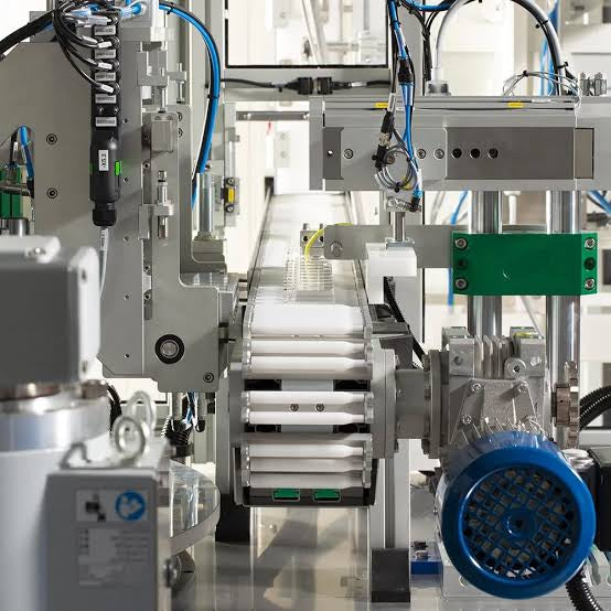
Mastering Modern Industrial Joystick Controls in Heavy Automation
Industrial joysticks play a pivotal role in human-machine interaction across heavy material handling and mobile hydraulics. These tactile controllers translate complex operator movements into precise electrical signals for PLCs, motion controllers, and DCS networks. Consequently, selecting and installing the right joystick architecture ensures operator safety, reduces fatigue, and optimizes equipment performance.

Navigating Industrial Automation Failures: Types, Causes, and Mitigation Strategies
Modern manufacturing relies heavily on automated control systems to maximize throughput and maintain product quality. However, unplanned downtime in industrial automation can cost facility operators thousands of dollars per hour. Understanding how programmable logic controllers (PLCs), distributed control systems (DCS), and field instrumentation fail empowers engineering teams to implement robust preventive maintenance strategies.