Understanding Why Your PLC Enters Stop Mode: Causes and Troubleshooting
- 〡
- 〡 por WUPAMBO
Introduction to PLC Operating Modes in Industrial Automation
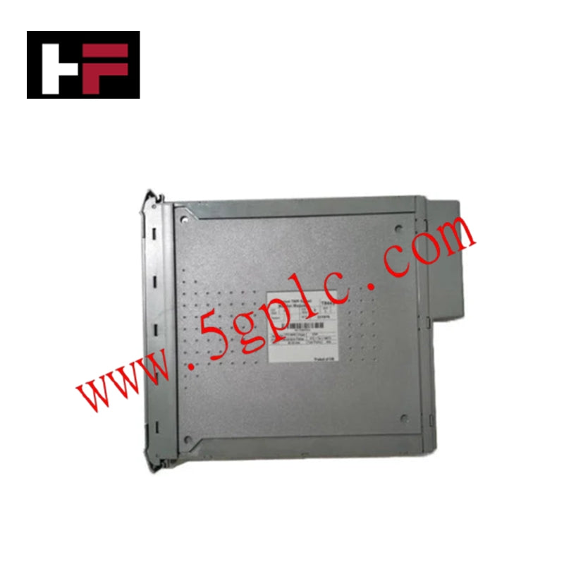
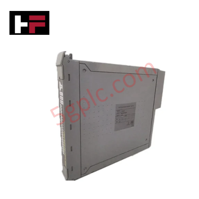
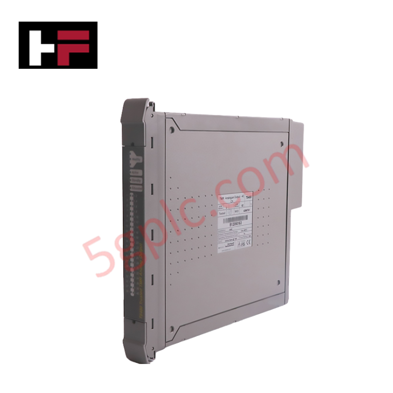
In industrial automation, programmable logic controllers (PLCs) serve as the core intelligence of modern factory automation and distributed control systems (DCS). Understanding how a PLC transitions between modes is vital for maintenance engineers. Typically, a PLC operates across four primary modes: Run, Stop, Start-Up, and Hold. When power is applied, the system immediately boots into Stop mode before initiating the Start-Up sequence. If the controller encounters a critical error during execution, it automatically reverts to Stop mode to prevent equipment damage. Therefore, monitoring these state transitions helps technicians maintain high system availability.
Identifying Critical Hardware Errors
Hardware failures represent one of the most common triggers for unexpected PLC Stop mode transitions. When diagnostic routines detect a severe physical fault, the controller immediately halts execution. For instance, internal wiring short circuits or power supply interruptions in I/O modules force the system into a protective Stop state. However, minor discrepancies, such as an unconfigured connected module, usually trigger an alarm rather than a complete shutdown. Consequently, maintenance teams must inspect diagnostic buffer logs to isolate physical wiring issues before rebooting industrial control systems.
Addressing Software Bugs and Runtime Exceptions
Programming errors and unhandled exceptions frequently cause PLCs to drop out of Run mode. Common software triggers include watchdog timeouts, numeric overflow errors, underflow anomalies, and infinite calculation loops. For example, programming an accidental division by zero prevents the CPU from processing the scan cycle, resulting in an immediate system halt. Therefore, software engineers must implement rigorous error-handling routines and bounds checking during PLC code development to ensure robust factory automation performance.
Managing Hardware and Digital Input Switches
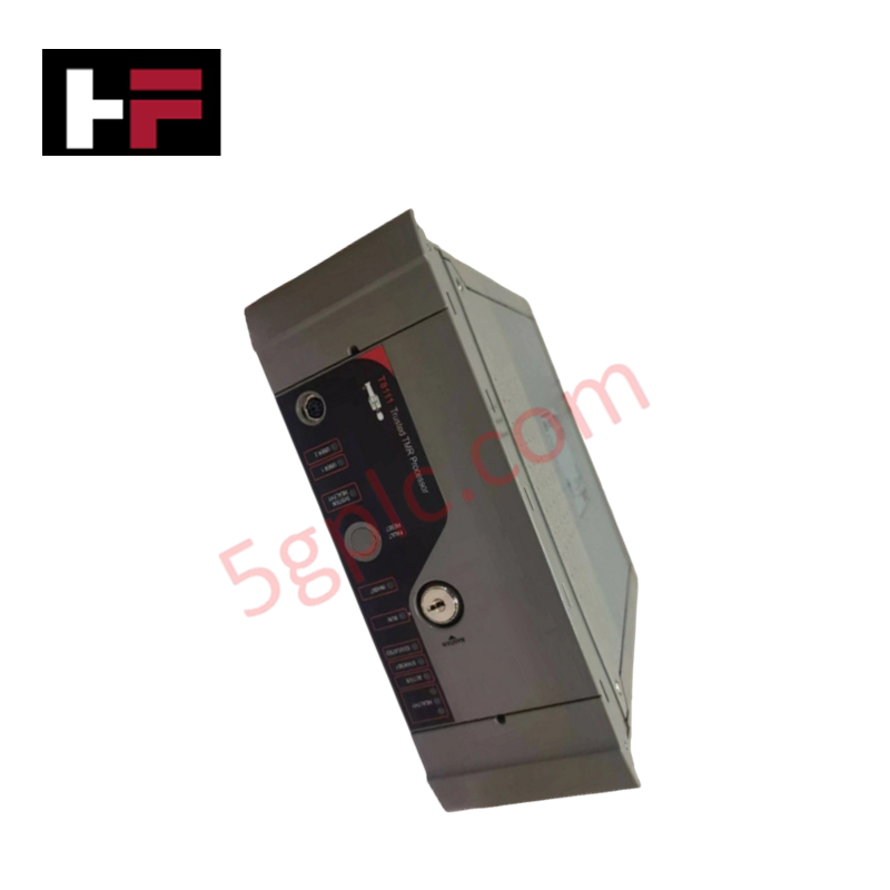
Physical switches and configured digital inputs provide direct manual control over PLC operating states. Many industrial controllers feature a physical Run/Stop toggle switch on the front panel, serving as an immediate emergency safety measure. Furthermore, advanced automation architectures allow engineers to assign a specific digital input function as a software-controlled Run/Stop interlock. If this designated input drops low, the controller restricts execution and remains in Stop mode. Technicians should always verify these hardware override states during initial commissioning.
Preventing Memory Mismatch and Download Failures
Improper memory management and programming deployment methods often lead to unexpected operational halts. In specific PLC platforms, technicians must manually execute a save command to store new configuration changes into non-volatile memory. If power is cycled without saving these changes, the system reverts to a safe Stop state. In addition, executing a full program download temporarily halts the CPU execution cycle. Automation professionals must schedule full downloads during planned maintenance windows to avoid unintended production downtime.
Securing Network Commands and Web Server Interfaces
Modern industrial automation hardware frequently embeds web server capabilities directly into the CPU modules. This advancement allows authorized programmers to monitor and manage PLC configurations via standard web browsers using the controller IP address. However, if an operator accidentally triggers a remote stop command through the network interface, the PLC will immediately switch to Stop mode. Therefore, facilities must implement strict cybersecurity protocols and access controls for all connected control systems.
Practical Application Scenario
Consider a continuous chemical processing plant where an unexpected PLC shutdown halts critical mixing valves. When the controller enters Stop mode due to a watchdog timeout caused by a data communication bottleneck, the system safely isolates the process loops. Maintenance engineers immediately access the CPU diagnostic screen via the engineering workstation, identify the overflow calculation in the logic block, correct the firmware routine, and restore the plant to normal operation without hardware replacement.
Author Profile
Zhang Wei is a Senior Industrial Automation Editor and Senior PLC Systems Specialist with over 15 years of hands-on experience designing, programming, and troubleshooting complex DCS and PLC architectures across global manufacturing and energy sectors. He regularly contributes technical insights to leading industrial automation publications, focusing on reliability centered maintenance and advanced control system diagnostics.
- Publicado em:
- automation engineering
- control systems
- DCS
- industrial controllers
- PLC
- PLC maintenance
- PLC stop mode
- PLC troubleshooting