










Product Details
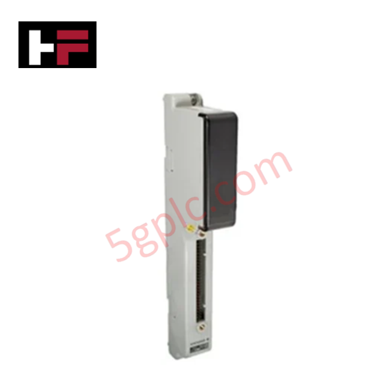
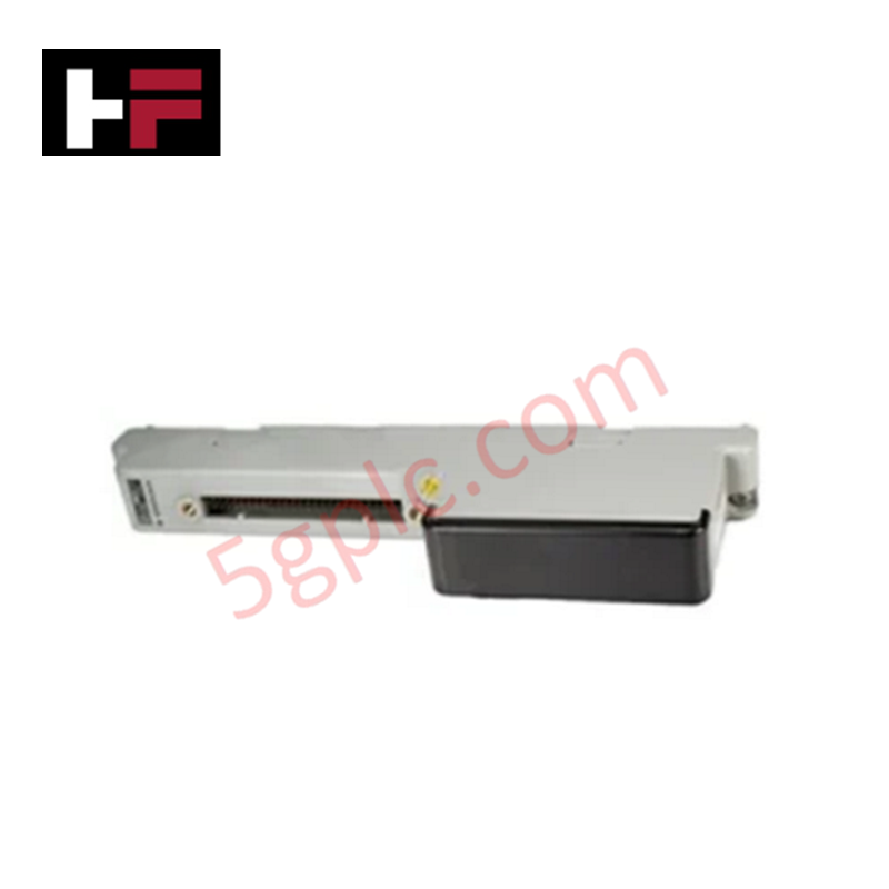
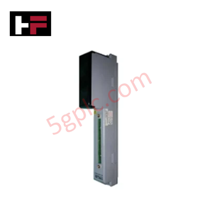
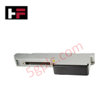
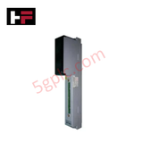
The YOKOGAWA ADM51, also cataloged as the ADM51 Contact Output Card, operates as a dedicated hardware component for discrete signal switching and relay execution within Yokogawa CENTUM CS 3000 distributed control system architectures.
Hardware Specifications
| Parameter | Specification |
|---|---|
| Model | ADM51 |
| Brand | YOKOGAWA |
| Origin | Japan |
| Weight | 0.1 kg |
| Dimensions | 22.9 cm x 2.5 cm x 7.6 cm |
| Output Channels | 16-point contact output |
| Contact Types | Mechanical relay or solid-state |
| System Compatibility | Yokogawa CENTUM CS 3000 DCS |
Channel-to-Channel Isolation and DCS Integration
The ADM51 contact output card interfaces discrete field actuators, solenoids, and alarm indicators with the CENTUM CS 3000 system backplane. Galvanic and channel-to-channel isolation barriers protect system control electronics from inductive kickback, field voltage surges, and common-mode interference. The discrete switching logic operates in parallel with 4-20 mA HART loop protocol analog sub-assemblies, providing deterministic state execution without inducing cross-talk on adjacent DCS I/O cards.
Frequently Asked Questions
Q: What output contact switching options are supported on the ADM51 card?
A: The card utilizes either mechanical relay or solid-state contacts across its 16 output channels to suit varied field voltage and load switching requirements.
Q: How does the ADM51 output card interface with field devices in a CENTUM rack?
A: The card mounts directly into the node rack and routes its 16 discrete contact outputs through dedicated backplane cabling to external field terminal blocks.
Field Installation Guidelines
De-energize field power supplies and the host node rack backplane prior to card installation or removal. Observe electrostatic discharge (ESD) protection procedures by wearing a grounded wrist strap when handling the card. Insert the ADM51 vertically along the rack guide rails until the backplane connector seats completely into the slot socket. Tighten top and bottom retaining screws to establish structural retention and frame grounding continuity. Route discrete output wiring separately from high-voltage AC lines and analog signal cables to prevent electromagnetic coupling. Ensure external inductive loads are wired with suppression circuits to prevent contact arcing during output state transitions.
Additional Information
- 100% Genuine Parts: All products are original and authentic, ensuring reliable industrial performance.
- 30-Day Refund Guarantee: Return any in-stock item within 30 days in original, unopened packaging for a full refund (excluding shipping and fees).
- 12-Month Warranty: Covers defects in materials or workmanship; excludes misuse, normal wear, or unauthorized modifications.
- Worldwide Shipping: We ship via USPS, UPS, FedEx, and DHL. Delivery times vary by country and may be subject to customs or import fees.
- Support & Contact: Technical and warranty assistance is available anytime. Contact us here: Contact.
- Purchase Guidance: Check product specifications and compatibility carefully before ordering to ensure proper application.


Tech & Buying Guide

Demystifying CPU Communication Ports in Siemens PLC Architectures
Industrial automation relies heavily on robust data exchange between devices. Without seamless connectivity, field instruments, network switches, human-machine interfaces, and programmable logic controllers cannot coordinate effectively. Therefore, understanding the various CPU communication ports available in Siemens hardware ensures efficient factory automation design and seamless system integration.

Mastering the Siemens PLC Scan Cycle: How the CPU Executes Automation Programs
Industrial automation relies heavily on programmable logic controllers (PLCs) to manage complex manufacturing processes. Many engineers dive straight into programming without mastering the underlying architecture. However, understanding how a PLC CPU executes a program ensures reliable system design. Therefore, mastering the scan cycle optimizes both performance and troubleshooting in modern control systems.

How to Connect to Siemens S7 PLCs: 5 Essential Communication Methods
Establishing a reliable hardware link between a programming terminal and a Siemens SIMATIC controller is essential for engineering workflows. Field engineers rely on distinct physical layers, ranging from legacy serial connections to high-speed Industrial Ethernet protocols. Modern factory automation environments prioritize fast data transfer and seamless driver integration. Selecting the correct connection method simplifies program downloads, online monitoring, and system troubleshooting in complex control systems.