


Product Details
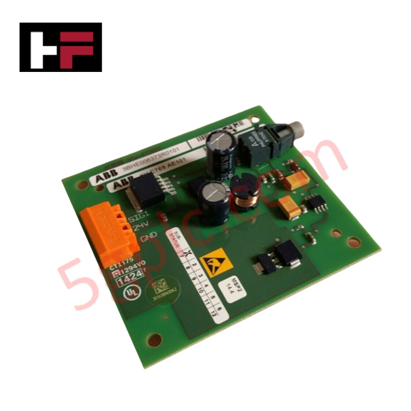
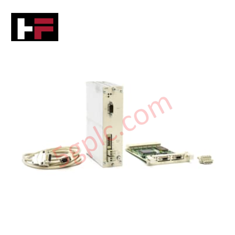
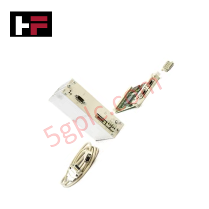
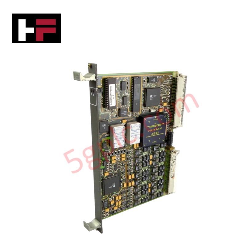
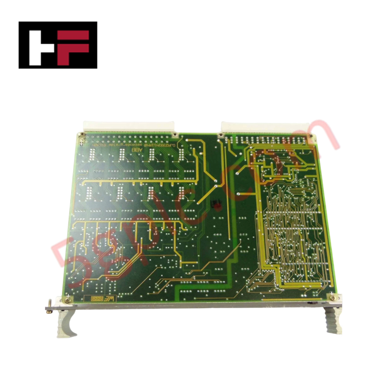
The ABB XV C769 AE101 (3BHE006373R0101 OEI-Board), also cataloged as the XVC769AE101 Interface Module, operates as a dedicated hardware component for optical-electrical interface signal processing within industrial control systems.
Hardware Specifications
| Parameter | Specification |
|---|---|
| Model | XV C769 AE101 |
| Brand | ABB |
| Part Number | 3BHE006373R0101 |
| Origin | Sweden |
| Weight | 0.35 kg |
| Dimensions | 230 mm x 110 mm x 34 mm |
| Operating Temp | Standard industrial ambient |
| Power Consumption | System backplane dependent |
Backplane bus communication velocity and firmware compatibility
The XVC769AE101 OEI-Board facilitates signal translation within the controller rack, maintaining deterministic backplane bus communication velocity essential for real-time data integrity. The module architecture is designed to support specific backplane protocols, requiring alignment with the host processor's I/O scanning cycles. Firmware flash compatibility is determined by the system revision; ensure the host controller firmware supports the XVC769AE101 hardware ID to prevent initialization errors. The board is optimized for I/O density scaling, allowing for high-speed signal propagation between the controller and the optical interface network without inducing measurable phase shift or packet latency.
Frequently Asked Questions
Q: Does the XVC769AE101 support hot-swapping during active system operation?
A: No. Hot-swapping is not supported. De-energize the host backplane completely before installing or removing the board to prevent electrical transients from damaging the communication interface and bus logic.
Q: How is signal integrity verified after installation?
A: Signal integrity is confirmed via the controller's diagnostic software through link-state monitoring. If the status registers report communication timeouts or parity errors, verify the mechanical seating of the board and the cleanliness of the optical interface ports.
Field Installation Guidelines
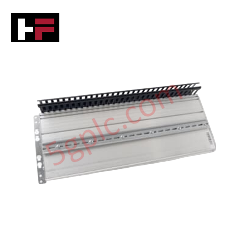
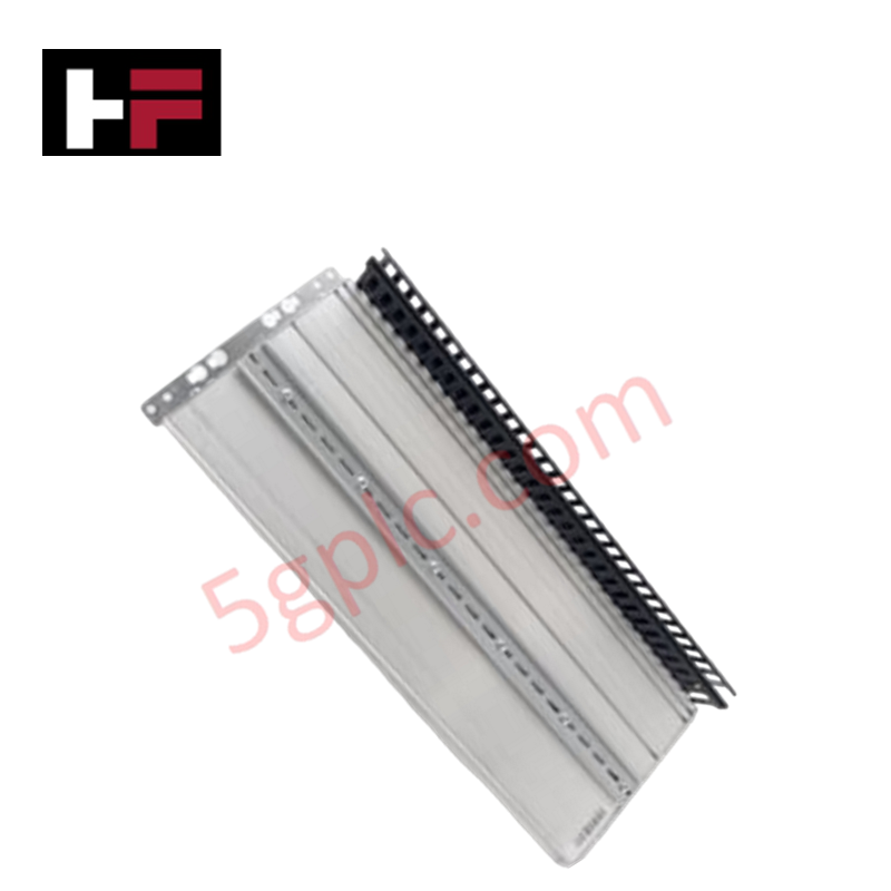
- Mounting: Ensure the board is aligned with the internal guide rails and fully inserted into the backplane connector. Verify that all locking pins are secured to prevent vibration-induced loosening.
- Grounding: The board chassis must be connected to the cabinet common ground. Utilize the mounting points to establish a low-impedance path, which is mandatory to minimize electromagnetic interference (EMI) on the signal traces.
- Signal Integrity: Route optical interface cabling according to the minimum bend radius specifications to prevent fiber optic signal attenuation or micro-fractures.
- Maintenance: Periodically check for dust accumulation on the board surface and optical connectors. Use dry, clean air or approved precision electronics cleaners to clear obstructions.
- Inspection: Before integration, inspect the backplane pins for signs of bending or oxidation. Ensure the PCB surface shows no signs of thermal stress or discoloration.
Additional Information
- 100% Genuine Parts: All products are original and authentic, ensuring reliable industrial performance.
- 30-Day Refund Guarantee: Return any in-stock item within 30 days in original, unopened packaging for a full refund (excluding shipping and fees).
- 12-Month Warranty: Covers defects in materials or workmanship; excludes misuse, normal wear, or unauthorized modifications.
- Worldwide Shipping: We ship via USPS, UPS, FedEx, and DHL. Delivery times vary by country and may be subject to customs or import fees.
- Support & Contact: Technical and warranty assistance is available anytime. Contact us here: Contact.
- Purchase Guidance: Check product specifications and compatibility carefully before ordering to ensure proper application.
Tech & Buying Guide

Essential Motion Control Commands: A Practical Guide for Engineers
Automation engineers often rely on precise position and speed control to drive modern factory machinery. Modern industrial systems, such as Programmable Logic Controllers (PLCs) and Distributed Control Systems (DCS), depend heavily on standardized motion instructions. Mastering these commands ensures operational safety, protects mechanical components, and optimizes cycle times across production lines.

The Role of Intrinsic Safety Barriers in PLC and DCS Architectures
Implementing robust protection in hazardous industrial environments represents a fundamental safety requirement in factory automation. Process facilities often handle volatile gases, dusts, and chemical agents that pose significant combustion risks. Consequently, control system engineers must deploy energy-limiting interfaces to isolate safe-area control cabinets from hazardous-area field instrumentation. This article examines the function, selection, and electrical principles of intrinsic safety barriers within modern PLC and DCS networks.

Architectural Selection and Scale Classification of PLC Systems in Industrial Automation
Selecting the correct control platform represents a foundational engineering decision in factory automation. System designers must carefully balance technical parameters against long-term operational requirements when implementing a Programmable Logic Controller (PLC). This article examines the critical evaluation metrics, physical scale classifications, and operational architectures of modern control systems.