












Product Details
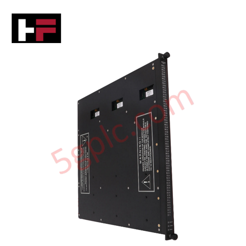
Configured for discrete signal switching in Tricon safety system platforms, the Triconex 3636R (3636R Relay Output Module) provides direct physical/electrical execution of 32 non-commoned relay outputs.
Hardware Specifications
| Parameter | Specification |
|---|---|
| Model | 3636R |
| Brand | Triconex |
| Dimensions | Standard Tricon module form factor |
| Operating Temp | Industrial standard range |
| Points | 32, non-commoned |
| Voltage Range | 125 VAC/VDC maximum |
| Current Load | 2 A maximum |
Fail-Safe State Execution and Output Logic
The Triconex 3636R is utilized for applications requiring non-triplicated relay output switching. As a non-TMR (Triple Modular Redundant) component, the module relies on the system's internal output processing logic to initiate contact state changes. The module supports a minimum permissible load of 10 mA at 5 VDC to ensure reliable contact wetting and minimize oxidation on the relay interface. In accordance with safety system design standards, the 3636R is configured for fail-safe state execution; upon the loss of communication with the logic solver or internal fault detection, the relay contacts transition to a pre-defined safe state to isolate the field-side load.
Frequently Asked Questions
Q: Does the 3636R support hot-swapping during active system operation?
A: The 3636R module is designed for hot-swap capability within the Tricon chassis. Verify that the relay load is de-energized or in a safe state before module extraction to prevent arcing at the backplane or output terminals.
Q: How should the non-commoned outputs be configured for external loads?
A: The non-commoned architecture allows each of the 32 points to switch independent voltage loops. Users must ensure that the voltage and current at each relay contact remain within the 125 VAC/VDC and 2 A maximum limits to prevent contact fusion.
Field Installation Guidelines
- Ensure the module is compatible with the physical slot configuration of the chassis backplane.
- Align the module carefully with the chassis rails to avoid pin damage, then apply firm pressure until the connector is fully seated.
- Secure the front-panel captive screws to ensure a solid electrical ground connection to the chassis frame.
- Route field wiring for each non-commoned relay circuit through separate conduits if required by voltage segregation standards to prevent cross-circuit coupling.
- Perform a functional verification test of all 32 relay contact states following installation to confirm correct logic mapping and field device response.
Additional Information
- 100% Genuine Parts: All products are original and authentic, ensuring reliable industrial performance.
- 30-Day Refund Guarantee: Return any in-stock item within 30 days in original, unopened packaging for a full refund (excluding shipping and fees).
- 12-Month Warranty: Covers defects in materials or workmanship; excludes misuse, normal wear, or unauthorized modifications.
- Worldwide Shipping: We ship via USPS, UPS, FedEx, and DHL. Delivery times vary by country and may be subject to customs or import fees.
- Support & Contact: Technical and warranty assistance is available anytime. Contact us here: Contact.
- Purchase Guidance: Check product specifications and compatibility carefully before ordering to ensure proper application.




Tech & Buying Guide

Understanding Siemens PLC Memory Cards: MMC, SMC, and SD Solutions in Industrial Automation
Memory management plays a pivotal role in maintaining control system reliability across modern manufacturing plants. Industrial control systems rely on specialized memory cards to store project logic, firmware updates, and retentive system data. Siemens uses several memory architectures, including Micro Memory Cards (MMC) and SIMATIC Memory Cards (SMC). Engineers must understand these hardware variations to ensure zero data loss and minimize downtime during maintenance routines.

Redefining Control Systems: The Rise of Flexible I/O Modules in Industrial Automation
Conventional input-output architectures often limit engineering agility and inflate long-term inventory costs. Today, Flexible Input/Output Modules (FIOM) are transforming how control system engineers design, commission, and maintain automation infrastructure. By allowing individual channel software configuration, FIOM technology bridges the gap between rigid hardware design and dynamic plant requirements.

Understanding Modern SCADA Systems: Architecture, Communication Topologies, and Industrial Applications
Supervisory Control and Data Acquisition (SCADA) systems form the digital backbone of modern industrial automation. They collect critical field data, transmit signals across vast distances, and empower plant operators with real-time process visibility. Across modern infrastructures, SCADA solutions streamline centralized control and maintain continuous operational uptime.