


Product Details
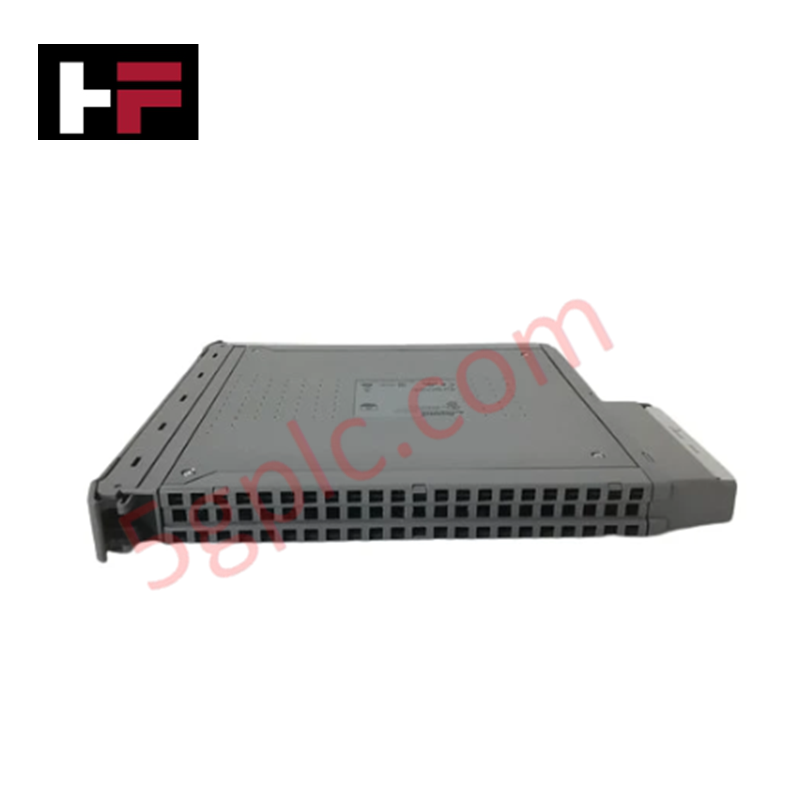
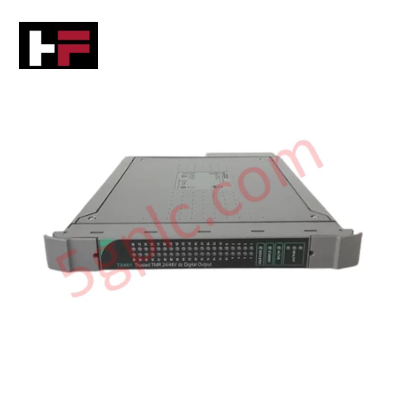
Configured for signal routing in Trusted TMR control systems, the ICS Triplex T8153 (T8153 Communications Interface Adapter) provides direct physical and electrical execution. The unit facilitates 32-channel signal output interfacing, managing 24 VDC digital loads with dedicated TMR-compliant processing paths to ensure synchronization across the control network.
Hardware Specifications
| Parameter | Specification |
|---|---|
| Model | T8153 |
| Brand | ICS Triplex |
| Origin | Not Specified |
| Weight | 0.8 kg |
| Dimensions | 16 cm x 16 cm x 12 cm |
| Operating Temp | -40 deg C to +70 deg C |
| Power Consumption | 6.5 W at 24 VDC |
| Output Channels | 32 (TMR) |
| Output Type | 24 VDC, 2 A per channel |
| Response Time | < 2 ms |
| Isolation Voltage | 1500 Vrms channel-to-bus |
Triple Modular Redundancy (TMR) Architecture
The T8153 utilizes a triple modular redundancy (TMR) 2oo3 architecture to execute output commands. Three independent internal logic processors verify output states through a voting mechanism. If a hardware discrepancy is detected within one of the three channels, the module isolates the faulty path, preventing erroneous signal propagation while maintaining continuous output control. This design ensures that the fail-safe state execution is triggered only upon confirmed system logic requirements, minimizing spurious interruptions in the output field loops.
Frequently Asked Questions
Q: Does the T8153 support online hot-swapping?
A: Yes, the module supports hot-swapping within a powered Trusted TMR backplane. Ensure that the associated system software is configured to ignore diagnostic alarms during the module extraction and replacement sequence to prevent unintended safety trips.
Q: What is the isolation capability of the channel-to-bus interface?
A: The T8153 provides 1500 Vrms galvanic isolation between the field-side output channels and the internal communication bus, providing protection against transient voltage spikes and ground potential differences between field devices and the controller backplane.
Field Installation Guidelines
- Verify the 18-30 VDC power supply range before mounting the module to the backplane.
- Align the T8153 guide rails with the backplane slots to ensure the connectors seat without physical resistance or pin deformation.
- Secure the module using the front-panel mounting screws to maintain electrical ground continuity through the chassis.
- Terminate field wiring using shielded cables; verify that the shield is grounded only at the specified system reference point to avoid ground loops.
- Confirm that the off-state leakage current remains below 1 mA for the connected load devices to ensure correct state detection.
Additional Information
- 100% Genuine Parts: All products are original and authentic, ensuring reliable industrial performance.
- 30-Day Refund Guarantee: Return any in-stock item within 30 days in original, unopened packaging for a full refund (excluding shipping and fees).
- 12-Month Warranty: Covers defects in materials or workmanship; excludes misuse, normal wear, or unauthorized modifications.
- Worldwide Shipping: We ship via USPS, UPS, FedEx, and DHL. Delivery times vary by country and may be subject to customs or import fees.
- Support & Contact: Technical and warranty assistance is available anytime. Contact us here: Contact.
- Purchase Guidance: Check product specifications and compatibility carefully before ordering to ensure proper application.


Tech & Buying Guide

Essential Motion Control Commands: A Practical Guide for Engineers
Automation engineers often rely on precise position and speed control to drive modern factory machinery. Modern industrial systems, such as Programmable Logic Controllers (PLCs) and Distributed Control Systems (DCS), depend heavily on standardized motion instructions. Mastering these commands ensures operational safety, protects mechanical components, and optimizes cycle times across production lines.

The Role of Intrinsic Safety Barriers in PLC and DCS Architectures
Implementing robust protection in hazardous industrial environments represents a fundamental safety requirement in factory automation. Process facilities often handle volatile gases, dusts, and chemical agents that pose significant combustion risks. Consequently, control system engineers must deploy energy-limiting interfaces to isolate safe-area control cabinets from hazardous-area field instrumentation. This article examines the function, selection, and electrical principles of intrinsic safety barriers within modern PLC and DCS networks.

Architectural Selection and Scale Classification of PLC Systems in Industrial Automation
Selecting the correct control platform represents a foundational engineering decision in factory automation. System designers must carefully balance technical parameters against long-term operational requirements when implementing a Programmable Logic Controller (PLC). This article examines the critical evaluation metrics, physical scale classifications, and operational architectures of modern control systems.