










Product Details
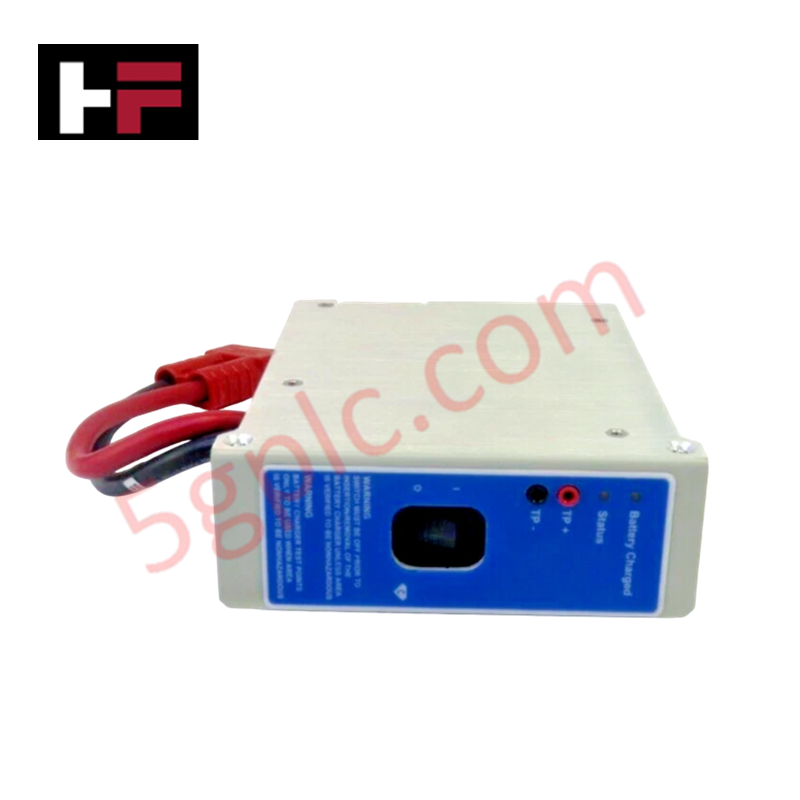
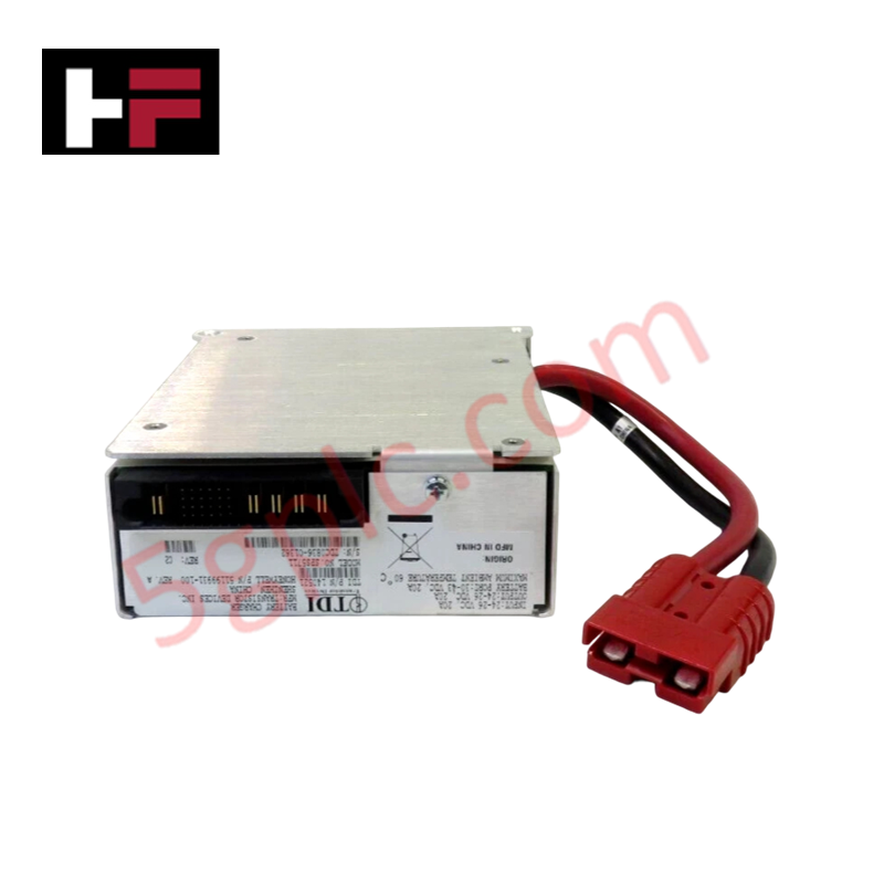
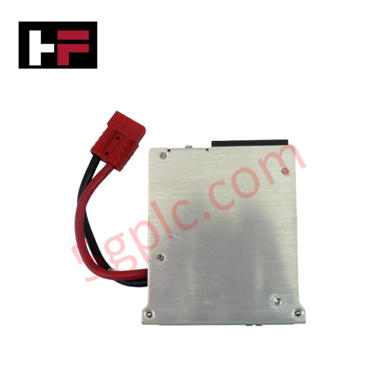
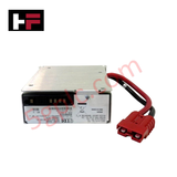
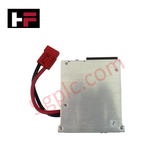
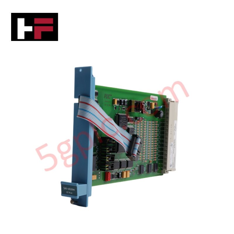
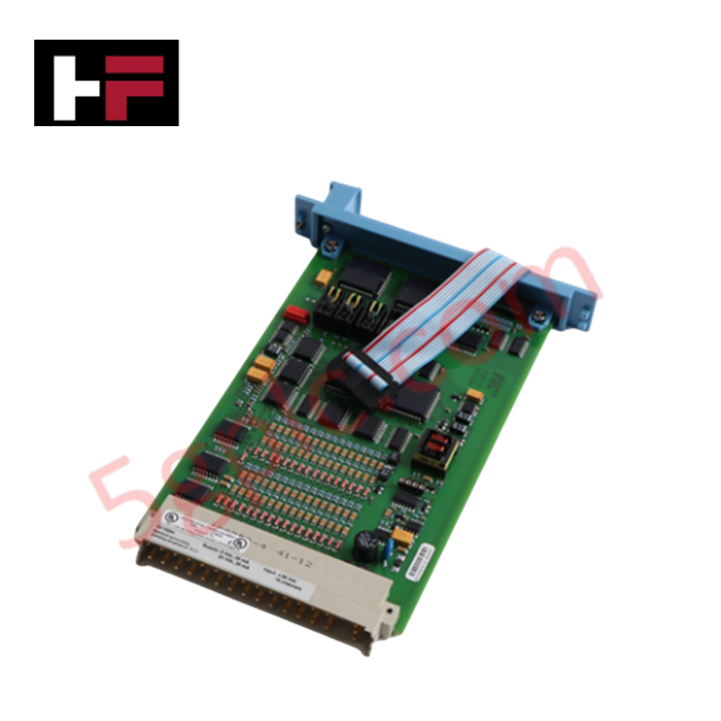
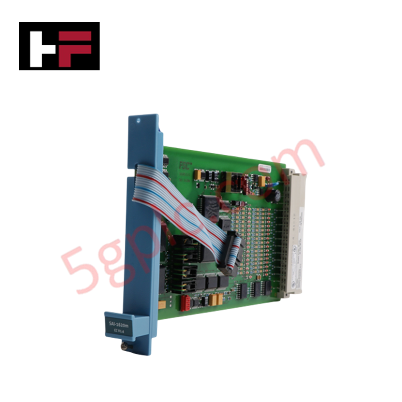
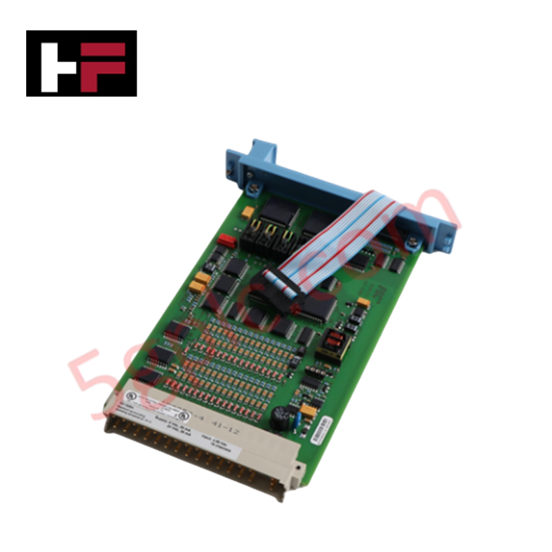
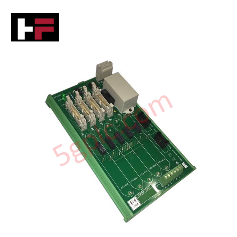
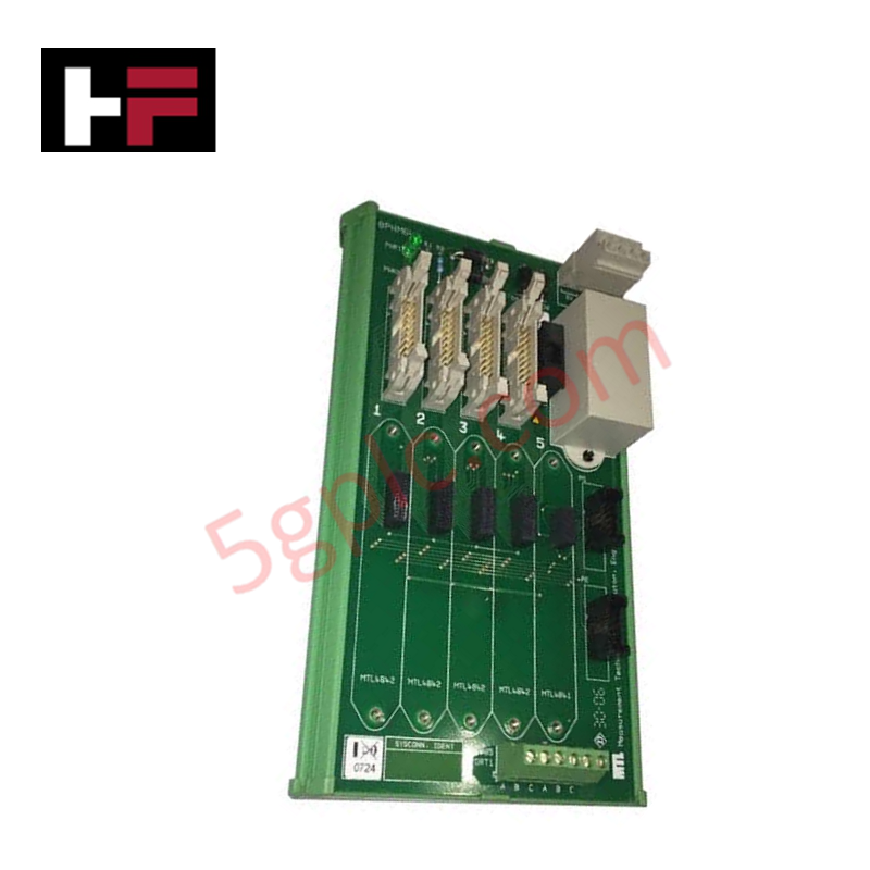
The Honeywell SPS5711 51199931-100, also cataloged as the 51199931-100 TDI Battery Charger, operates as a dedicated hardware component for continuous backup power management and regulated battery charging within Honeywell TDC 3000 networks. Accepting an input voltage range of 24 to 26 VDC, the unit conditions and delivers a regulated 30 to 43 VDC output to downstream battery ports at a continuous rating of 20 A. This module prevents power bus dropouts during primary supply interruptions by maintaining steady-state DC reserve levels across connected control chassis.
Hardware Specifications
| Parameter | Specification |
|---|---|
| Model | SPS5711 51199931-100 (Rev D) |
| Brand | Honeywell |
| Origin | USA |
| Weight | 1.06 kg |
| Dimensions | Standard TDC 3000 chassis slot sizing |
| Operating Temp | -20 to +60 deg C |
| Power Consumption | System bus driven (20 A output rating) |
| Input Voltage | 24-26 VDC |
| Output Voltage | 30-43 VDC (Battery Port) |
| Current Rating | 20 A continuous |
4-20 mA HART Loop Protocol & Channel-to-Channel Isolation
The SPS5711 51199931-100 incorporates high-efficiency internal power conversion circuits designed to prevent high-frequency switching noise from propagating into sensitive field wiring paths. Internal galvanic channel-to-channel isolation decouples the 24-26 VDC input bus from the 30-43 VDC battery charge loop, suppressing common-mode electrical noise. This structural filtering prevents power rail ripple from causing inductive interference or signal distortion on adjacent 4-20 mA HART loop protocol lines running through shared enclosure raceways.
Frequently Asked Questions
Q: What happens if the input voltage drops below the 24 VDC threshold during operation?
A: The charger logic detects under-voltage conditions and disengages the primary charging circuit to prevent reverse current drain from the battery assembly into the input supply bus.
Q: Can the SPS5711 51199931-100 module be replaced while the TDC 3000 system is powered?
A: Module removal requires isolating the continuous 20 A battery charging output terminals first to eliminate arcing risks across the backplane connector pins.
Field Installation Guidelines
- Slide the module into its designated rack slot until the backplane power connectors are fully seated and engaged.
- Tighten all mechanical retaining screws on the front panel to establish a solid ground bond with the cabinet frame.
- Route input and output DC power conductors separately from low-level analog and communication cabling to avoid EMI noise coupling.
- Verify that cabinet ambient airflow pathways remain unobstructed to ensure heat dissipation does not exceed the +60 deg C thermal rating under full 20 A continuous load.
Additional Information
- 100% Genuine Parts: All products are original and authentic, ensuring reliable industrial performance.
- 30-Day Refund Guarantee: Return any in-stock item within 30 days in original, unopened packaging for a full refund (excluding shipping and fees).
- 12-Month Warranty: Covers defects in materials or workmanship; excludes misuse, normal wear, or unauthorized modifications.
- Worldwide Shipping: We ship via USPS, UPS, FedEx, and DHL. Delivery times vary by country and may be subject to customs or import fees.
- Support & Contact: Technical and warranty assistance is available anytime. Contact us here: Contact.
- Purchase Guidance: Check product specifications and compatibility carefully before ordering to ensure proper application.
Tech & Buying Guide

The Shift to Flexible IO Modules in Modern Industrial Automation
Traditional control systems rely on dedicated Input Output (IO) cards for industrial automation. Each conventional module processes a single signal type, such as Digital Input (DI), Digital Output (DO), Analog Input (AI), or Analog Output (AO). A standard 16-channel card accepts only one specific channel type across all ports. This inflexible hardware design often creates severe engineering bottlenecks during project execution. Engineers frequently must install entirely new cards to accommodate a single extra sensor. Consequently, late design changes increase control cabinet space requirements and drive up project costs.

DCS Commissioning Steps in Industrial Automation Projects
Commissioning a Distributed Control System (DCS) represents a crucial milestone when deploying modern process automation infrastructure. Field engineers must execute systematic verification steps to transition complex control hardware from static installation to dynamic plant control. Proper commissioning ensures that controllers, I/O modules, network switches, and HMI software operate in strict compliance with engineering design specifications before introducing live process fluids.
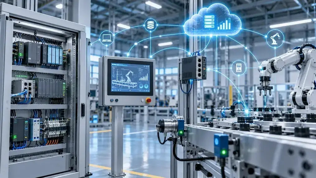
PLC and DCS Control System Spares Strategy: Engineering Guidelines
Modern factory automation relies on high-speed fiber optic backbones to link distributed control systems across noise-intensive industrial environments. Unlike copper wiring, optical fibers transmit data via light pulses, making them completely immune to electromagnetic interference (EMI). Field engineers must master optical cable joining and fusion splicing techniques to guarantee low-loss data transmission across critical Programmable Logic Controller (PLC) and Distributed Control System (DCS) nodes.