










Product Details
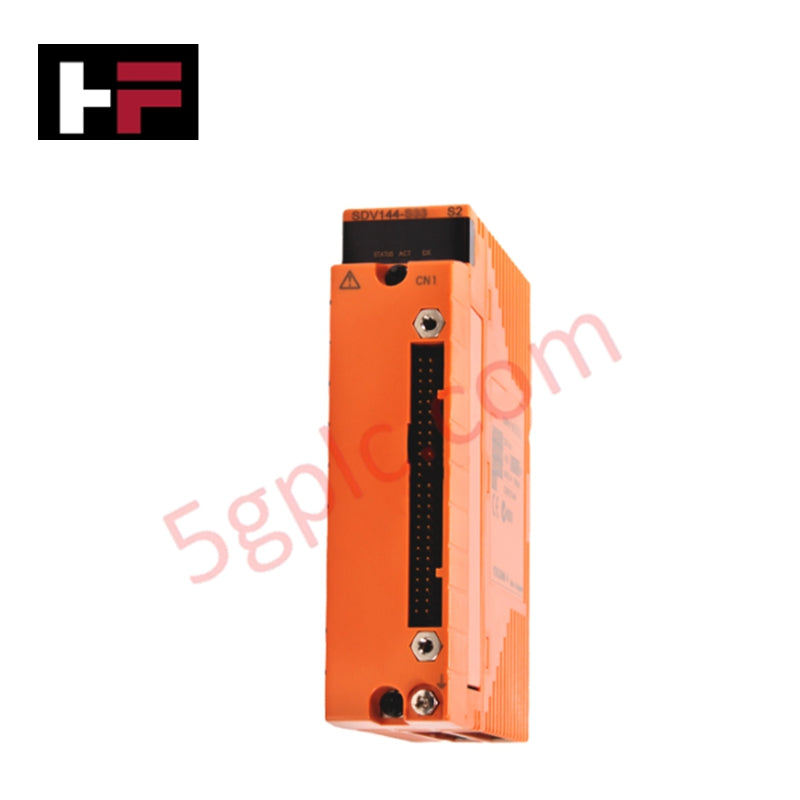
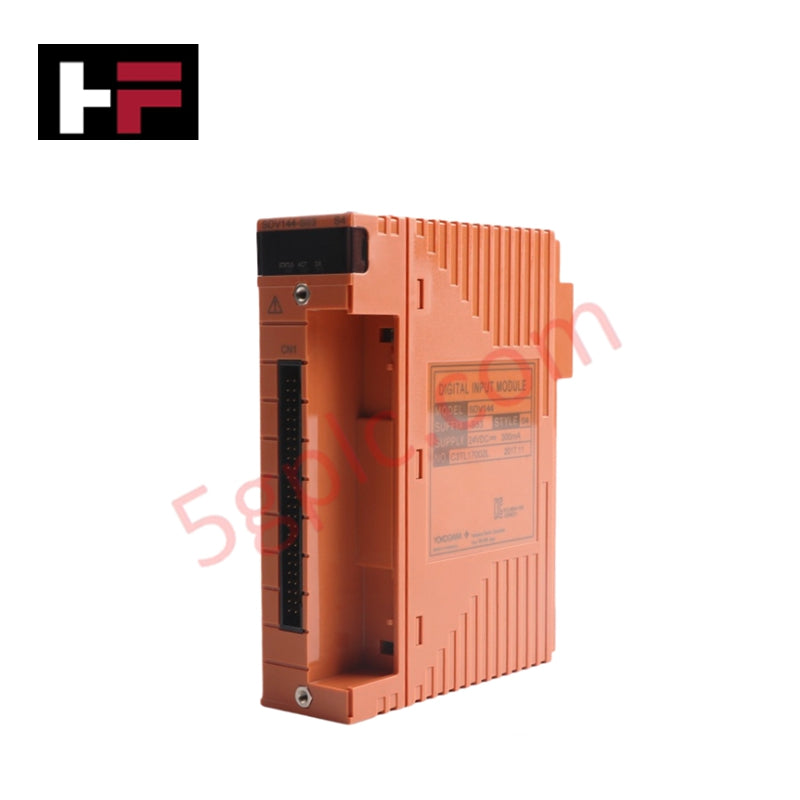
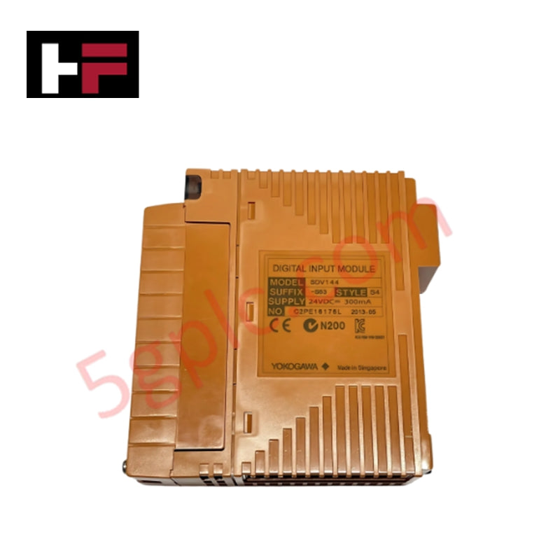
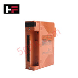
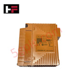
Configured for isolated binary status monitoring in ProSafe-RS safety instrumented system networks, the Yokogawa SDV144-S53/B4S00 (SDV144 Digital Input Module) provides direct physical/electrical execution. The hardware operates 16 discrete input channels to interrogate no-voltage contact signals from field devices, transmitting validated electrical state data directly to the safety logic bus.
Suffix Breakdown & Model Matrix
- -S: Standard hardware type platform profile.
- 5: Designed for pressure clamp terminal block interface or MIL cable assembly; non-explosion protection housing configuration.
- 3: Includes ISA Standard G3 conformal coating with an extended operating temperature rating from -20 to +70 deg C.
- /B4S00: Option code specifying an integrated terminal block connection assembly with built-in surge absorber mechanisms for signal loop hardening.
Hardware Specifications
| Parameter | Specification |
|---|---|
| Model | SDV144-S53/B4S00 |
| Brand | Yokogawa |
| Origin | Japan |
| Weight | Approx. 0.36 kg (with pressure clamp terminal interface) |
| Dimensions | Standard Yokogawa ProSafe-RS I/O slot footprint |
| Operating Temp | -20 to +70 deg C |
| Power Consumption | 290 mA maximum @ 5 VDC, 140 mA maximum @ 24 VDC from system backplane |
| Input Channels | 16 isolated channels |
| Input Signal | No-voltage contact: ON (1 k ohm maximum), OFF (100 k ohm minimum) |
| Input Current | 6 mA +/-20% (External power supply: 24 VDC, 0 ohm input loop) |
| Contact Rating | 24 VDC +20% / -10%, 10 mA or greater |
| External Power Supply | 24 VDC +20% / -10%, current capacity 200 mA |
| Instantaneous Max Input Voltage | 30.0 VDC |
| Input Response Time | 40 ms maximum |
| Withstand Voltage | 2 kV AC between input signal and system logic for 1 minute |
| Environmental Tolerance | ISA Standard G3 conformal coating class |
Process Control & Channel-to-Channel Isolation
The module architecture leverages galvanic module isolation parameters to decouple incoming field-side 24 VDC instrumentation loops from the internal processing core. Internal optocouplers establish a strict electrical barrier that withstands up to 2 kV AC for 1 minute, preventing field-side voltage spikes, ground shifts, or inductive transients from corrupting system memory. This structural isolation suppresses high-frequency cross-talk and ensures exact signal demarcation, protecting the logic execution pathway within dual-redundant safety loops.
Frequently Asked Questions
Q: How does the module handle a field-side contact resistance drift that exceeds the stated specifications?
A: The hardware logic relies on precise input state thresholds. If a field switch contact degrades, causing the ON resistance to exceed 1 k ohm or the OFF resistance to fall below 100 k ohm, the internal detection circuits will fail to register the correct state transition within the 40 ms window, generating an unvalidated loop status on the controller bus.
Q: What are the functional requirements for implementing dual-redundant module configurations?
A: Dual-redundancy requires pairing two identical SDV144 modules on adjacent baseplate slots connected to a shared or parallel terminal block matrix. The internal ProSafe-RS bus arbitrates cross-checking diagnostics between both modules, maintaining input signal processing continuity without disruption if one hardware unit experiences a fatal logic or power fault.
Field Installation Guidelines
- Chassis Insertion and Vertical Alignment: Slide the module vertically into its assigned baseplate position until the top and bottom retention clips snap completely into place. Maintain unrestricted cabinet clearance around the ventilation apertures to ensure proper heat dissipation across the -20 to +70 deg C operational threshold.
- Shield Grounding and Drain Wire Termination: Instrumentation cable shields must be stripped, combed, and tied directly to the single-point cabinet ground busbar. The field instrument side of the shield must float to prevent common-mode ground currents from looping back through the 24 VDC wetting supply lines.
- Surge Absorber Verification: The /B4S00 option features internal surge protection. Field wiring conductors must be properly tensioned within the pressure clamp terminals to ensure low contact resistance, allowing transient energy spikes to route safely to the structural ground without blowing out the input channels.
Additional Information
- 100% Genuine Parts: All products are original and authentic, ensuring reliable industrial performance.
- 30-Day Refund Guarantee: Return any in-stock item within 30 days in original, unopened packaging for a full refund (excluding shipping and fees).
- 12-Month Warranty: Covers defects in materials or workmanship; excludes misuse, normal wear, or unauthorized modifications.
- Worldwide Shipping: We ship via USPS, UPS, FedEx, and DHL. Delivery times vary by country and may be subject to customs or import fees.
- Support & Contact: Technical and warranty assistance is available anytime. Contact us here: Contact.
- Purchase Guidance: Check product specifications and compatibility carefully before ordering to ensure proper application.


Tech & Buying Guide
Comprehensive Guide to PLC Types in Modern Industrial Automation
Modern industrial automation relies on programmable logic controllers to govern critical factory operations. System integrators classify PLCs based on scale, hardware architecture, and power supply design. Understanding these core categories enables automation engineers to select the right control system architecture. Consequently, proper hardware selection optimizes performance while minimizing long-term operational costs.

Demystifying the DDE Protocol in Legacy Industrial Automation Systems
Modern control systems rely heavily on seamless interprocess communication to exchange operational data between software programs. Microsoft first introduced the Dynamic Data Exchange (DDE) protocol in 1987 to enable real-time data sharing. In factory automation, DDE served as an early bridge between control software and Windows desktop applications. Therefore, understanding DDE mechanics provides crucial insights into how legacy industrial networks established software-level connectivity.

Demystifying CPU Communication Ports in Siemens PLC Architectures
Industrial automation relies heavily on robust data exchange between devices. Without seamless connectivity, field instruments, network switches, human-machine interfaces, and programmable logic controllers cannot coordinate effectively. Therefore, understanding the various CPU communication ports available in Siemens hardware ensures efficient factory automation design and seamless system integration.