


Product Details
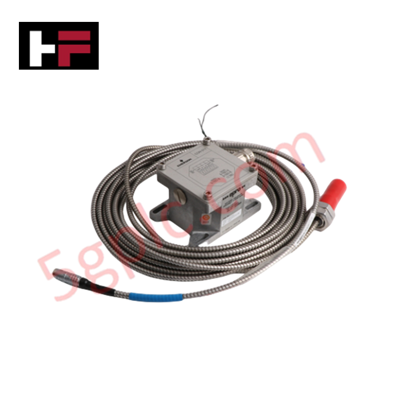
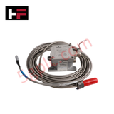
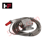
Configured for non-contact displacement monitoring in rotating machinery networks, the Emerson Epro PR6424/010-100+CON021 (PR6424/010-100) Eddy Current Sensor Kit provides direct physical execution of radial and axial dynamic shaft displacement and speed acquisition.
Hardware Specifications
| Parameter | Specification |
|---|---|
| Model | PR6424/010-100+CON021 |
| Brand | Emerson Epro |
| Origin | Not Specified |
| Weight | 0.20 kg (Sensor) |
| Dimensions | M18x1.5 sleeve thread, 40 mm length |
| Operating Temp | -35 deg C to 150 deg C (Sensor) |
| Power Consumption | 23 VDC to 32 VDC (Converter) |
| Probe Diameter | 16 mm |
Mechanical Monitoring and TSI Integration
The PR6424 sensor utilizes eddy-current induction to determine the proximity of a ferromagnetic shaft. To maintain valid rotor dynamics data, the system requires precise eddy-current probe scaling, ensuring the voltage output accurately tracks the 4 V/mm sensitivity rating. During installation, users must perform gap voltage validation, targeting a -10 VDC offset to ensure the probe remains within its linear measurement range. The system incorporates cross-talk suppression by utilizing shielded PTFE cabling and Lemo-plug termination, which prevents electromagnetic interference from corrupting the high-frequency dynamic signal required for eccentricity and key-phasor speed detection.
Frequently Asked Questions
Q: Can the cable length of the PR6424/010-100 be modified in the field?
A: No. The PR6424 sensor and CON021 converter comprise a factory-calibrated signal chain. Modifying the 5 m cable length will alter the system impedance and resonant frequency, leading to significant errors in measurement accuracy and linearity.
Q: What is the requirement for the shaft material monitored by this sensor?
A: The sensor is calibrated for ferromagnetic steel (42 Cr Mo4 standard). Monitoring shafts constructed from non-ferromagnetic materials will result in non-linear responses and reduced measurement sensitivity, requiring factory recalibration.
Field Installation Guidelines
- Mounting: Secure the sensor within a rigid, non-vibrating bracket. Use the M18x1.5 thread for positioning, ensuring the probe tip is clear of the shaft surface throughout all operational conditions.
- Gap Adjustment: Establish the nominal 2.7 mm air gap using a calibrated feeler gauge. Verify that the sensor is positioned at the center of its linear range to allow for both radial and axial shaft excursions.
- Grounding and Shielding: Route the armored coaxial cable away from high-voltage power lines and VFD drive outputs. Terminate all cable shields to a dedicated instrument ground bus to mitigate noise induction.
- Connector Maintenance: Inspect the Lemo-plug connections for moisture or conductive debris. Ensure the self-locking mechanism is fully engaged to prevent intermittent signal loss caused by vibration.
Additional Information
- 100% Genuine Parts: All products are original and authentic, ensuring reliable industrial performance.
- 30-Day Refund Guarantee: Return any in-stock item within 30 days in original, unopened packaging for a full refund (excluding shipping and fees).
- 12-Month Warranty: Covers defects in materials or workmanship; excludes misuse, normal wear, or unauthorized modifications.
- Worldwide Shipping: We ship via USPS, UPS, FedEx, and DHL. Delivery times vary by country and may be subject to customs or import fees.
- Support & Contact: Technical and warranty assistance is available anytime. Contact us here: Contact.
- Purchase Guidance: Check product specifications and compatibility carefully before ordering to ensure proper application.


Tech & Buying Guide

Understanding Dry Contacts in PLC Wiring: An Industrial Automation Guide
Mastering contact switching principles is essential for reliable control panels. Field devices and PLCs interface through dry or wet contacts. This technical guide examines the mechanics of dry contacts, explores their wiring architectures, and evaluates their key advantages in industrial automation.

Ultimate Commissioning Checklist for Industrial Automation Systems: An Engineering Guide
Commissioning is the most decisive phase of an industrial automation project, transforming control hardware and software into an operational facility. Thorough testing prevents costly startup delays and builds customer confidence. This guide covers essential checklists, electrical standards, and best practices.

Redundant Automation Systems: Core Architecture, Business Value, and Technical Advantages
Unplanned downtime poses a major financial threat to process manufacturing. To prevent costly interruptions, engineers deploy redundant PLC and DCS architectures that ensure continuous operation when hardware fails. This technical guide explores redundancy principles, critical system nodes, and real-world scenarios.